APOLLO
11 OPERATIONS HANDBOOK BLOCK II SPACECRAFT
VOLUME
l SPACECRAFT DESCRIPTION
Image Table of Contents - Pinch, Zoom, and Click on the Component to get Information
Table of Contents
Spacecraft
Launch Vehicle and Booster Combination Diagram
LAUNCH VEHICLE AND
BOOSTEER CONFIGURATION
APOLLO SPACECRAFT
CONFIGURATION
Block
II Spacecraft Reference Stations Diagram
Block
II Spacecraft Configuration Diagram
Boost
Protective Cover Diagram
Block
II Command Module Diagram
CM
External Compartments Diagram
Apollo
Crew Compartment Diagram
Crew Compartment and
Equipment Bays
CM
Internal Configuration Diagrams
Closeout
and Protection Panels Diagram
Stowage Compartments and Lockers Diagram
Controls and Displays Panel Numbering System Diagram
Apollo Foldable Crew Couch Structure Diagram
Foldable Couch Components Diagram
Foldable Couch Positions Diagram
Seatpan, Legpan, Armrest, and Footpan Mission Positions
Seatpan, Legpan, Armrest, and Footpan Mission Positions Diagram
Foldable Couch Adjustments Diagram
Foldable Couch Adjustment Procedures
Legpan - Footpan Positions Diagram
Preparing Couches for EVA Procedures
Stowing the Center Couch Diagram
Preparing
Coach for EVA Diagram
CM Hatch Counterbalance Schematic
CM Internal Configuration Diagram
The Apollo Operations Handbook consists of two volumes,
I and 2. Volume l is the Spacecraft Description and Volume 2 is the
Operational Procedures, Volume I has three sections: section I describes
Apollo spacecraft general structure and mechanical systems; section 2
describes the Apollo spacecraft systems; and section 3, the Apollo
spacecraft controls and display. Volume 2 continues with two procedural
sections: section 4 lists the steps of normal and backup procedures: of
all mission phases; and section 5 contains the contingency procedures for
aborts, malfunctions, and emergencies.
Section l first describes the launch vehicle boosters
that propel the Apollo spacecraft and lunar module (LM) into earth orbit
and translunar injection. This description is followed by a fore to aft
description of the Apollo spacecraft, which includes the launch escape
assembly, command module with mechanical systems, service module, and the
spacecraft lunar module adaptor.
The spacecraft launch vehicle and booster combination
have various designations. The following chart summarizes the mission
letter designator, Apollo number, launch vehicle designator, and CSM
number for the manned flights. A mission is defined and then given a
letter I designator; thus, the Mission Letter Designator. The Apollo
Number designates the numerical order 0f launching, manned or unmanned,
and if used primarily as a news media reference. The Launch Vehicle
Designator indicates the booster configuration of the launch vehicle. The
200 series designates the Saturn IB and the 500 series designates the
Saturn V. The command service module (CSM) assigned to the mission has a
CSM number designator of three digits.
Spacecraft Launch
Vehicle and Booster Combination Diagram
|
Mission Letter Designator |
Apollo Number |
Launch Vehicle Designator |
CSM NUMBER |
|
Mission C |
Apollo 7 |
Saturn 1B (205) |
101 |
|
Mission D |
Apollo 8 |
Saturn V (503) |
103 |
|
Mission E |
Apollo 9 |
Saturn V (504) |
104 |
|
Mission F |
Apollo 10 |
Saturn V (505) |
106 |
|
Mission G |
Apollo 11 |
Saturn V (506) |
107 |
|
Mission H-1 |
Apollo 12 |
Saturn V (507) |
108 |
|
Mission H-2 |
Apollo 13 |
Saturn V (508) |
109 |
|
Mission H-3 |
Apollo 14 |
Saturn V (509) |
110 |
When improvements to the spacecraft systems are made,
the system is modified. Modifications take effect on different spacecraft
so the term “effectively” is used. The effectivity of the Apollo
spacecraft systems in this handbook is for GSM 106 and subsequent (subs)
unless otherwise stated.
LAUNCH VEHICLE AND
B00STEER CONFIGURATION 1.1
The launch vehicle used in the Apollo program is
illustrated in the Apollo
Launch Vehicle Diagram. The Saturn V is programmed for earth
orbital missions and/ or lunar missions. The general configuration of the
launch vehicle boosters is summarized in the following paragraphs.
The Saturn V is a three-stage vehicle consisting of an
S-IC first stage, S-II second stage, and an S-IVB third stage.
First
Stage S-lC Booster 1.2.1.1
The S-IC ls manufactured by the Boeing Company and uses
five Rocketdyne F-1 engines. Each F-1 engine, burning RP-1 and liquid
oxygen, produces 1,500,000 pounds of thrust for an overall first stage
boost of 7,500,000 pounds of thrust. One engine will be rigidly attached
at the stage centerline, while the others will gimbal for vehicle control.
Second
Stage S-II Booster 1.2.1.2
The S-II, or second-stage, is manufactured by the Space
Division 0f North American Rockwell Corporation. The second-stage employs
five Rocketdyne J-2 engines.Each J-2 engine burns liquid hydrogen and
liquid oxygen, and produce 200,000 pounds of thrust for an overall
second-stage boost of 1,000,000 pounds. The gimbaled engines will be
mounted in a square pattern, with the fifth engine rigidly mounted in the
center.
Third
Stage S-IVB Booster 1.2.1.3
The S-IVB Third-Stage is manufactured by McDonnell
Douglas Corporation. The S-IVB employs a single Rocketdyne J-2 engine,
burning liquid hydrogen and liquid oxygen to produce 200,000 pounds of
thrust.
APOLLO
SPACECRAFT CONFIGURATION 1.3
The Block II spacecraft consists of a launch escape
assembly (LEA), command module (CM), service module (SM), the spacecraft
lunar module adapter (SLA), and the lunar module (LM). The reference
system and stations are shown in the
Block II Spacecraft Reference
Stations Diagram.
Block II Spacecraft
Reference Stations Diagram
LAUNCH
ESCAPE ASSEMBLY 1.3.1
The LEA (Block
II Spacecraft Configuration Diagram) provides the means for
separating the CM from the launch vehicle during pad or suborbital aborts.
This assembly consists of a Q-ball instrumentation assembly (nose cone),
ballast compartment, canard surfaces, pitch control motor, tower jettison
motor, launch escape motor, a structural skirt, an open-frame tower, and a
boost protective cover (BPC). The structural skirt at the base of the
housing, which encloses the launch escape rocket motors, is secured to the
forward portion of the tower. The BPC (Boost Protective Cover Diagram)
is attached to the aft end of the tower to protect the CM from heat during
boost, and from exhaust damage by the launch escape and tower jettison
motors. Explosive nuts, one in each tower leg well, secure the tower to
the CM structure. (For additional information, refer to the sequential
systems in section 2, subsection
2 .9).
Block II Spacecraft
Configuration Diagram
Boost Protective
Cover Diagram
COMMAND
MODULE 1.3.2
The CM (Block
II Command Module Diagram), the spacecraft control center,
contains necessary automatic and manual equipment to control and monitor
the spacecraft systems; it also contains the required equipment for safety
and comfort of the flight crew. The module is an irregular-shaped, primary
structure encompassed by three heat shields (coated with ablative material
and joined or fastened to the primary structure) forming a truncated,
conic structure. The CM consists of a forward compartment, a crew
compartment, and an aft compartment for equipment and a crew. (CM External Compartments Diagram)
Block II Command
Module Diagram
CM External
Compartments Diagram
The command module is conical shaped, 11 feet 1 .5
inches long, and 12 feet 6.5 inches in diameter without the ablative
material. The ablative material is non-symmetrical and adds approximately
4 inches to the height and 5 inches to the diameter.
Forward
Compartment 1.3.2.1
The forward compartment (figure
1-6) is the area outside the forward access tunnel, forward of the
crew compartment forward bulkhead and covered by the forward heat shield.
Four 90-degree segments around the perimeter of the tunnel contain the
recovery equipment, two negative pitch reaction control system engines,
and the forward heat shield release mechanism. Most of the equipment in
the forward compartment consists of earth landing (recovery) system (ELS)
components.
The forward heat shield is made of brazed stainless
steel honeycomb covered with ablative material. It contains four recessed
fittings which permit the launch escape tower to be attached to the CM
inner structure. Jettison thrusters separate the forward heat shield from
the CM after entry or after the LEA 1s separated during an abort.
Aft
Compartment 1.3.2.2
The aft compartment (CM External Compartments)
is the area encompassed by the aft portion of the crew compartment heat
shield, aft heat shield, and aft portion of the primary structure. This
compartment contains ten reaction control engines, impact attenuation
structure, instrumentation, and storage tanks for water, fuel oxidizer,
and gaseous helium. Four crushable ribs, along the spacecraft +z axis, are
provided as part of the impact attenuation structure to absorb energy
during impact.
The aft heat shield, which encloses the large end of
the CM, is a shallow, spherically contoured assembly. It is made of the
same type of materials as the forward heat shield. However, the ablative
material on this heat shield has a greater thickness for the dissipation
of heat during entry. External provisions are made on this heat shield for
connecting the CM to the SM storage tanks for water, fuel oxidizer, and
gaseous helium. Four crushable ribs, along the spacecraft +z axis, are
provided as part of the impact attenuation structure to absorb energy
during impact.
The aft heat shield, which encloses the large end of
the CM, is a shallow, spherically contoured assembly. It is made of the
same type of materials as the forward heat shield. However, the ablative
material on this heat shield has a greater thickness for the dissipation
of heat during entry. External provisions are made on this heat shield for
connecting the CM to tl1e SM.
Crew
Compartment 1.3.2.3
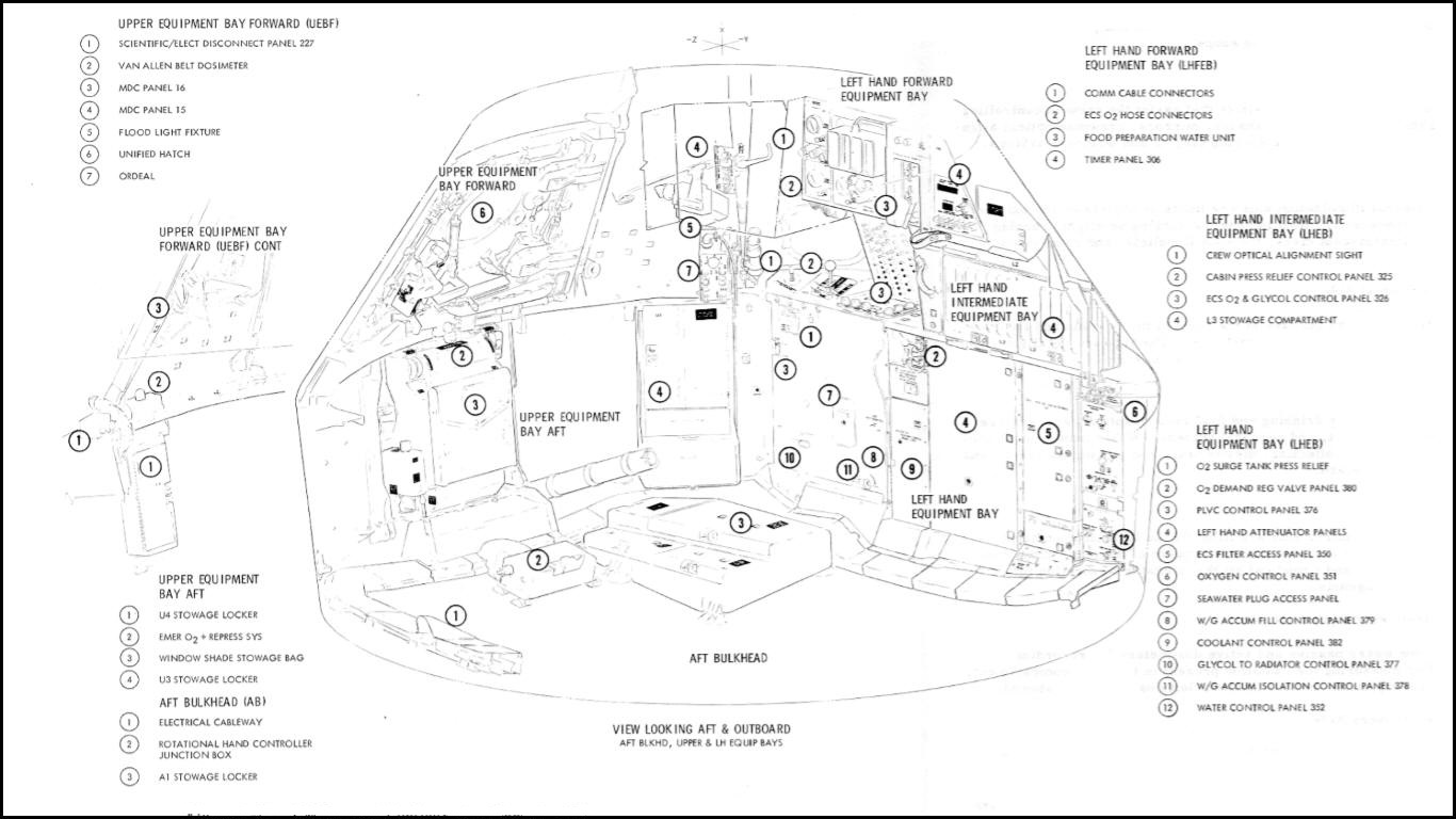
The crew compartment or inner structure (Apollo Crew Compartment Diagram)
is a sealed cabin with pressurization maintained by the environmental
control system (ECS). The compartment, protected by a heat shield,
contains controls and displays for operation of the spacecraft and
spacecraft systems, crew couches and restraint harness assemblies, hatch
covers, window shades, etc., and is provided with crew equipment, food and
water, waste management provisions, and survival equipment. Access
hatches, observation windows, and equipment bays are attached as part of
the compartment structure. The interior volume is 366 cubic feet. However,
the lower, right, and left equipment bays, lockers, couches, and crewman
occupy 156 cubic feet, leaving a usable volume of 210 cubic feet.
Apollo Crew
Compartment Diagram
The crew compartment heat shield (Block II Command Module Diagram)
, like the forward heat shield, is made of brazed stainless - steel
honeycomb and covered with ablative material . This heat shield, or outer
structure , contains the SC umbilical connector outlet, ablative plugs, a
copper heat sink for the optical sighting ports in the lower equipment
bay, two side observation windows, two forward viewing windows, and the
side access hatch.
Crew
Compartment and Equipment Bays
1.3.2.3.1
Each crew member has personal and accessory equipment
provided for his use in the crew compartment. Major items of personal
equipment consist of a spacesuit assembly with attaching hose and
umbilical, a communications assembly, biomedical sensors, and radiation
dosimeters. Major items of accessory equipment shared by the crew consist
of an in-flight tool set and a medical kit. For a detailed list of crew
equipment, refer to section 2 .12. General items contained
in the CM equipment and stowage bays are listed in
CM Internal Configuration
Diagram.
CM
Internal Configuration Diagrams
The protection panels prevent loose equipment (tools,
etc.) and debris from getting into the various nooks and crevices in the
crew compartment. They also suppress fire by closing out the equipment
bays with covers around the aft bulkhead, and protect the ECS tubing from
the zero g activities of the crew and the prelaunch activities of ground
personnel. The location and configuration of the protection panels are
illustrated in the Closeout
and Protection Panel Diagram.
Closeout and
Protection Panels Diagram
The protection panels (also referred to as close - out
panels) are a series of aluminum panels and covers that fair the irregular
structure to the equipment bays and wire troughs and covers. The panels
vary in thickness and are attached to secondary structures by captivated
fasteners. Access panels and penetrations are located at or over equipment
and connectors needed for the mission.
Loose
Equipment
Stowage
1.3.2.3.3
The stowage
of numerous
items
of personal
and systems
loose
equipment
is in compartments
and
lockers
(Stowage
Compartments and Lockers).
Compartments
are
part
of
the
crew
compartment
structure.
Equipment
is
placed
in
"cushions"
and inserted
in
to the
compartments.
The aluminum
lockers
are
packed
with equipment
in
an
assembly
building
and are
quickly
attached
to
the
aft
bulkhead
and equipment bays a short
time
before
launch.
This allows aft bulkhead access during
spacecraft
ground
processing.
The compartment and locker doors have squeeze-type
latches
and can
be
opened and closed with one hand.
Stowage Compartments
and Lockers
SC Controls
and Displays
1.3.2.4
The controls
and
displays (panels,
switches,
gages,
valve
handles,
etc.)
for
operation
of
the
spacecraft and its
systems
are located throughout
the
crew
compartment.
The location,
nomenclature,
function,
and
power source of the
controls
and displays are
provided
in section 3.
The
panel numbers
indicate
the
equipment bay and area of
location.
The
panel
numbering
system
is
shown
in
Controls and Displays Panel Numbering System.
For
instance,
the 100 to
199
series
will
be
located
in the
lower
equipment
bay
(LEB).
The LEB
is divided
into
panel
areas such as
100-1
19
in
the upper
left,
120
-
139
in the
upper
center,
etc.
The advantage
of
this
system is (given a panel
number
and
knowing
the numbered areas)
to
enable the crew to pinpoint
the
area and
locate
the
panel
very
quickly.
Controls
and Displays
Panel
Numbering
System
Crew Couches
1.3.2.5
The primary
function
of
the
couches
i
s
to
support the
crew
during
accelerations/decelerations
up to 30 g forward
and
aft
(±X),
18
g
up
and
down
(±
Z),
and
15
g
laterally
(±Y).
Because
the critical
g-load
is during landing,
an attenuation
system
is
used
to
reduce the
deceleration
load
on the crew.
There are two attenuation
subsystems,
external
and
internal.
Secondary function of
the
crew couches
is
to
position crew
at duty
stations and provide
support for
the translation
and
rotation hand controls, lights, and other equipment.
The couches
are
designated
(structurally)
as left, center, and right; by crew position
they
are
(left
to
right)
Command (CDR),
CSM
Pilot
(CMP), and LM Pilot
(LMP).
CM Impact
Attenuation
System
1.3.2.5.1
During
a water impact,
the CM deceleration
force
will
vary
from
12
to 40g,
depending
on
wave
shape
and horizontal velocity
at impact. The
impact
attenuation
system reduces
the
impact
forces
on
the
crew
to
a
value
within their
tolerance
level.
A
major
portion
of
the energy
(75 to
90 percent) is absorbed by the impact surface (water) and
the
deformation
of
the
CM structure. The impact system is
divided
into two subsystems: external and internal,
which
are
described
in the following
paragraphs.
External
Attenuation.
The
external attenuation
subsystem consists
of
four crushable
ribs
installed
in
the aft compartment
(External
Attenuation System Diagram).
The
ribs,
located
between
the
inner and
outer
structure
in the vicinity
of
the
+ Z
axis,
are
constructed of bonded
laminations
of
corrugated aluminum.
The CM
is
suspended, during
atmospheric
descent,
at
a
27
.5-degree angle (hang angle) by the parachute subsystem.
Because
of
the
hang
angle,
the first point of contact at
impact is
in the area
of
the crushable ribs.
External Attenuation
System
Diagram
Internal
Attenuation.
Eight attenuation struts are provided
for
connecting the crew couches
to
the
CM
inner structure.
Each strut
is capable
of absorbing energy at a
predetermined
rate through
"cyclic
struts."
The
cyclic strut utilizes
cyclic
material deformation concept
of
energy
absorption
by rolling ductile
metal
torus
elements
(bracelets)
in
friction
between a concentric
rod and cylinder.
The force
applied
to the
struts
causes the bracelets to roll,
absorbing
energy (Internal Attenuation System).
Two
Y
- Y axis
struts
·are
located
at the outer extremities of
the couch assembly at the hip
beam.
The cylinder end
of each strut
is
firmly
attached to the unitized couch while the
piston
end,
containing
a
flat circular
foot
,
reacts against
a
flat bearing
plate (attenuation
panel) attached
to
the structure.
Internal
Attenuation
System
Two
Z-Z axis
struts
are
attached
to
the side
stabilizer beams
and
the
aft
bulkhead
of the structure,
just below
the
side
access
hatch. Four X-X axis
struts
are
attached
to the forward CM structure and
the
beam
extremities of the couch.
These struts,
except for the
addition of
a
lockout mechanism, are basically
the same
as
the
Z
-
Z axis
struts.
A
lockout mechanism
is provided
on each X-X
strut to
prevent
any
strut
attenuation
prior to
landing (during
normal
mission
flight loads).
After
deployment
of the main parachute,
the "lockouts"
are manually
unlocked.
After
deployment of the
main
chutes
and
prior to
landing,
the "lockouts" are manually unlocked.
Foldable
Couch Structure
1.3.2.5.2
The
foldable
couches are
supported similarly
to the unitized
couch structure,
but the
individual
couches
differ.
The back
pan angle
to the
Y
-
Z plane
(horizontal) has been increased to 4
degrees
30 minutes.
Description.
The
couch
structure utilizes
two strong side stabilizer beams for attachment of the foot
XX and
ZZ
attenuator
struts and
a cross
-
member
head
beam
for
attachment
of the head XX attenuator struts.
The
left, center, and right couches are attached to the head beam by a
hinge/ pip
pin
and
are
attached to the side stabilizer beam by a
large
Marmon-type
clamp
(Apollo
Foldable Crew Couch Structure Diagram).
Apollo
Foldable
Crew
Couch
Structure Diagram
Each
couch consists of a
headrest,
body
support with backpan,
seatpan,
legpan
,
and footpan.
The
left
couch has two controller supports/armrests,
inboard
and
outboard.
The
right couch
has
only
the inboard,
or
left,
armrest.
Support for
the body is accomplished by a
web
or
Armalon
(multiple layers of
fiberglass
beta cloth, impregnated
and covered
with Teflon) over the support
frame from
the l1eadrest to
the
footpan (Foldable
Couch Positions Diagram).
Foldable
Couch Components
Diagram
The
Marmon
clamps
that
attach
to the side stabilizer
are part
of
the hip Y
-
Y beam.
·The
body support
frame will
rotate around it’s attach point on
the
head beam and can
fold
at the shoulder beam.
The
shoulder
straps
of
the
restraint
harness and
one-half of the lap
belts are solidly attached
to the shoulder beam.
Controller
supports/
armrests
rotate
and are attached
to the body
support
tubes
in
the area of the crewman's
elbow
and have
various
positions.
The left
couch
outboard
armrest has 65-, 90-, 120
-,
and
180-degree positions,
measured from the backpan, and supports the translation control (Foldable
Couch Positions Diagram).
The other
two
armrests have
65-,
90-, 125-,
and 180-degree positions. The armrests are
held
in position by a spring-loaded
wedge
into
a slotted cam. The wedge is attached to a
sleeve
around
the armrest.
To
rotate the armrest, the sleeve
is
lifted, the wedge pulled
out of
the cam,
and
the
armrest
rotated to the
desired position.
To
extend the
armrest,
rotate the extension.
The
rotational and
translation
controls
are
locked
on a
dovetail
by extending
a pin; however,
the controlling button extends into the center couch area. There
is a
danger of the
center
crewman bumping
the
control lock button
and
retracting the
pin;
therefore, a lock
is on
the shaft to prevent the button from being actuated accidentally.
Foldable
Couch
Positions
Diagram
The
control support (with dovetail) pitches up and down, and is locked
and
unlocked at
its
pivot by a cam
lever.
The
control support pivots to allow the correct
positioning
of the translation or
rotation
control during
docking
and the normal mission phases.
The
seatpan
(seat)
angles are 9,
85,
170, and 270 degrees. The
9
-degree
position
is held
by a detent, the 85- and 170-degree positions
are
lockable,
and
the
seat travel
is
stopped
at
270 degrees. The seatpan controls
are
located on the body supports at each side
of
the hips.
The seat
locked
position is with the
lever
footward;
the
unlocked
position
is
with the lever headward. One-half
of the
lap
belt is attached to the seatpan
frame.
The
seatpan
is connected to the legpan
frame
at
the knee
beam in a 78-degree
angle.
The
knee
control
on each side
of
the couch
locks
and
unlocks the
seatpan
to legpan angle.
Unlocked,
the seatpan-
to-legpan
angle
will
go
to
15
degrees
(folded),
and to
180 degrees (flat).
The footpan has
two
positions, 95
degrees
and folded
(O degrees).
There
are mechanical
stops
at
each
position.
The
footpan
has
two cleats
and
clamps
which
restrain
the boots
when
properly
engaged.
Seatpan, Legpan, Armrest, and
Footpan
Mission
Positions.
During
the mission
phases,
there is a
need
to place
the
couch
components
into
various positions.
The
following
chart indicates the positions of
the
couch
components
during
launch,
boost, entry,
and
landing;
egress-ingress
to
center
couch
to
LEB
and
tunnel
activities;
EVA
ingress
or egress;
and
docking.
Seatpan, Legpan, Armrest, and
Footpan
Mission
Positions Diagram
Foldable
Couch Adjustments.
The
couch
has
many adjustments that can be
performed
during the
mission. The
following chart
gives
a step
by
step procedure
for
making the
adjustments, beginning with
the
headrest
and progressing to the
footrest.
Because the couches are actuated in training
during
1
g,
the
1-g procedures
are
given
also.
Foldable
Couch Adjustment Procedures
|
Task |
Procedure |
Results/ Remarks |
|
|
NOTE |
|
|
|
·
Directions
are
for
person lying on couch. |
|
|
|
·
Inboard/outboard
movements – relative to
couch. |
|
|
A.
Headrest adjustment,
headward
- footward
movement
of
6
.5 in. |
1.
Lift
control
knob
(gearshift) toward head.
2.
Hold
gearshift
knob
in unlocked
position
and slide
headrest to desired position.
3.
Release
gearshift
knob. |
1.
Disengages
lock.
2.
Lock
is
spring-loaded
to
locked
position. |
|
B.
Armrest
adjustments |
|
|
|
B1.
Armrest rotation
or
pitching
(Armrests
lock
in
65°,
90°,
120° (L)
and 125
°
(R)
positions) |
1.
Lift armrest
handle.
2.
Rotate (pitch)
armrest
to desired position. (Wedge will engage at next slot
unless
handle
is lifted continually.) |
1.
Disengages wedge
from slotted
cam.
2.
Wedge
is
spring-loaded
to locked
position.
NOTE
When
rotating the
outboard
armrest
of
the
left couch, caution
should
be
exercised
to
prevent
the
positional
control column
from hitting
the stowed O2 hose as damage may result
to either
object. |
|
B2. Armrest
extension
(0
-
3.75
in.)
(Armrest
Position Diagram) |
1.
Rotate
armrest
extension
lock
ring away
from
couch.
2.
Extend control
to desired position.
3.
Lock
into
position
by
rotating lock ring towards couch. |
1.
Full
throw of about 160°
will
unlock sleeve.
2.
Pulls sleeve
out
of
barrel.
3.
Cam
will lock barrel
to
sleeve. |
|
B3.
Control
support
pitching
(Translation
control
pitch
=
0
°
-55
°)
(Rotational
control
pitch
=
0 °-25 °) (Armrest
Position Diagram) |
1.
Move end
of control support
cam
lever.
2.
Holding
control
or handle,
pitch
it
to
desired angle.
3.
Move end
of cam lever
down and
outboard. |
1.
Unlocks
control
support.
3
Locks
control
support. |
|
B4.
Control
attachment and locking, unlocking
(Armrest
Position Diagram) |
1.
Press
control
lock
button down
and
swing lock hook
away.
2.
Press control lock button
inboard.
3.
Slide
control
onto
support dovetail.
4.
Press
control
lock button
outboard.
5.
Swing
lock
hook
to button and
hock,
on
shaft (inboard
armrests
only). |
1.
Unlocks
button
so shaft can slide.
2.
Retracts control
lock pin.
3.
Attaches control
to support.
4.
Extends
control
lock
pin,
locking
control onto
support.
5.
Prevents control
lock
button
from sliding
to
unlocked
position. |
|
C.
Seatpan
adjustment |
|
|
|
C1.
Zero g seatpan
adjustment,
mid
mission
application (Seatpan
locks
in
11°, 85°, 170°/stops
at 270°.) |
1.
Place
both seatpan
handles in unlocked
position
(headward).
2.
Move seatpan
to
desired position.
3.
Place
one handle
in
locked
position
(footward). |
1.
Disengages seatpan latches.
Seatpan
free
to move.
3
One lock
is
sufficient in
zero
g. |
|
C2.
One g or
greater seatpan
adjustment,
training, preflight,
test,
launch
and entry application. (During
one
g,
stand
at
LEB
to adjust
seatpan.) |
1.
Support
seatpan
(with
hands or feet)
and
place
both
seatpan
handles
in
unlocked
position
(headward).
2.
Move
seatpan
to
desired
position,
maintain support.
3.
Place
both seatpan
handles
in
locked position (footward). |
1.
Damage
may
result
to
mechanisms
if
seatpan
is
allowed to drop
to
next
position.
2.
Same as 1
3.
In one
g
or
greater,
both
latches
may be
locked
to reduce strain on mechanisms. |
|
D.
Legpan to seatpan
adjustment
(15°, 78°)
(During zero
g, use
one
control.
During
one
g or
greater,
use both controls
and
support legpan during movement.) |
1.
Pull knee
control
out
and up to unlocked
position.
2.
Position
legpan to desired position.
3.
Pull
knee control
out and down to locked
position. |
1.
Retract knee control pin from slotted
cam.
3
Extends
knee control |
|
E.
Footpan
adjustment
(0°-95°)
(figure
1
-
18) |
1.
Swing footpan
to
desired position. |
1.
Mechanical stops at 0°
95°. |
|
E1. Engaging-disengaging
foot
restraints (Legpan
Footpan Position Diagram) |
1.
Place both spacesuit boots
or entry boots on
footpan
with heels together.
2.
Move
boots
outboard while heels slide on
footpan
.
3.
To
disengage, move boots
inboard while heels slide on
footpan. |
1.
Pre
positioning
boots.
2.
Footpan
cleats
will engage boot heels.
3.
Cleats will disengage from
boot
heel. |
|
|
|
|
Seat Pan
Positions Diagram
Armrest
Positioning
Diagram
Legpan
-
Footpan
Positions
Diagram
Foldable Couch
Mission
Operations.
During
the mission, there are tasks into which
the
couches are integrated.
The
following table indicates some
of
those
tasks
and
gives
a step by step
procedure.
Figures
are
also referenced.
Task
A, Preparing Couches for
EVA,
describes the
folding
of
the L-shaped PGA stowage bag and the removing and stowing of the
center couch
in preparation for
EVA.
The removal and stowage of the
center
couch can also
be performed when the center aisle needs
to
be
cleared
for
intra
vehicular
maneuvering
purposes.
In
addition to clearing the
center
aisle for
EVA,
the whole couch structure (couches plus side beams and
head beam) have to be stabilized when
the
foot X-X struts are disconnected.
This operation is described
in
task B.
Preparing Couches for
EVA Procedures
|
Task |
Procedure |
Results/Remarks |
|
A.
Preparing
couches for EVA |
|
|
|
A1. Stow L PGA bag on
aft Bulkhead |
1. Remove PGA helmet shield and
stow
in helmet bag.
2.
Unstrap bag
hip
straps and detach couch clips.
3. Fold lower half of bag
flat,
tucking sides.
4.
Fold
top
half
of
bag
flat, tucking sides.
5.
Attach bag top straps to
aft bulkhead
fittings. |
1.
Empties
PGA
bag.
2. Detaches
forward
top of bag
from
couch.
4. Bag now
flat on
aft
bulkhead.
5.
Bag now
lashed to aft
bulkhead. |
|
A.2 Remove
center
couch to aft
bulkhead (Crewman
standing
in
LEB)
(Stowing
Center Couch Diagram)
NOTE
If
the center couch is to
be
removed during one
g conditions,
the
outboard
(left and right) couches should not
be occupied.
Otherwise, extreme difficulty will
be
experienced during the removal. |
1.
Fold
footpan to 0
°,
lock
legpan
to
15 °,
and lock
seatpan to 11
°.
(figure
below)
2.
Pull center couch hip clamp knobs down 2
in.
(toward
aft
bulkhead).
3.
Using
knob,
unscrew shaft (CCW) until it is
flush
with trunnion.
4.
Swing
knob towards
LEB opening clamp.
5.
Retract
one Y - Y strut. (Y-Y
Strut Retraction Diagram)
6a. During
zero
g, force center couch toward aft bulkhead and disengage couch
from
clamp plates. During one g, place.
6b. clamps in intermediate position
as
a caution.
Hold
center couch backpan firmly while forcing couch toward aft
bulkhead until couch disengages.
Fully
open clamps and lower hip end of couch to
aft bulkhead.
7.
Move headrest
footward.
(Seatpan
Position Diagram)
8. Pull head
beam
pip pins
(2).
(Seatpan
Position Diagram)
9.
Lower
couch
to aft
bulkhead
on top of
PGA
bag. |
1.
Preparing couch.
2.
Knob
engages shaft.
3.
Trunnion will be
free to
rotate.
4.
Relieves pressure on clamp
plate.
6a. Frees
footward
end
of
couch
from
clamps. (Couch structure may have to be
shaken.)
6b. Clamps
in
intermediate
Position will support couch if it slips. Outboard
couches may
have
to be lifted to take pressure off center couch clamp plates.
7.
Prep for strapping
under
left couch.
8.
Disconnects
headward
end of
couch
from head
beam
9. Couch is
now
ready to stow. |
|
A3.
Stow
center couch under left couch |
1.
Obtain
lower
(3.5
ft x
2 in.)
and
upper
(4 ft x 2
in.) restrainer straps from
stowage locker.
2.
Thread lower strap hooks (2) through center couch hip holes from
inside.
3.
Wrap upper strap around center couch headrest support bars and
attach snap to ring.
4.
Verify
left
couch headrest
fully
headward.
5.
Position
center couch under left couch, firmly pressing against tunnel
hatch bag.
6.
Attach LOWER
strap
hooks
to left couch
D-rings.
7.
7.
Unsnap
UPPER strap
hook,
resnap after
wrapping
around
left
couch headrest support
bars. |
2.
Preparing center
couch
to
strap
to
left couch.
5.
Head-to-head, hip-to
hip,
and piggy back.
6.
Hip ends of couches
now secured
7.
Head
ends of couches
now
secured. |
|
B. Preparing
couch structure for EVA;
(Preparing
couch structure for EVA) |
|
|
|
B1. Connect
EVA
stabilizer
strut
to couch. |
1.
Unstow
EVA
stabilizer
strut
by
squeezing
latch
and pulling
toward
couch.
2.
Connect EVA
stabilizer strut to couch structure
at
aft end of right head
strut.
Engage
stabilizer strut and press toward aft bulkhead. |
1.
2.
With EVA stabilizer
strut
engaged,
couch
structure will
be stabilized
when foot
struts are
disconnected. |
|
B2. Disconnect foot attenuator
struts
and attach to forward equipment bays. |
1.
Grasp
the
quick
disconnect
hook
assembly, pull
lock
pin
actuator
toward lower
equipment
bay.
2.
Pull
lower end of foot
attenuator
strut
(quick-disconnect
hook
assembly) firmly
toward LEB
until
it disengages.
3.
Repeat for other
foot
X-X
attenuator strut.
4.
Swing attenuator struts along
side
of forward equipment
bay, and strap. |
Holding lock pin actuator
in
disengages
lock
pin.
Holds attenuator
struts
out
of the way
.for
increased
mobility
in
LEB. |
Stowing
the
Center Couch
Preparing Coach for
EVA Diagram
CM Mechanical Controls
1.3.2.6
Mechanical controls are provided in the crew compartment for manual
operation of tl1e
s
ide
access
hatch covers,
forward
access hatch covers, and
manual
override levers for
the
ECS cabin
pressure relief valve. Tools
for
emergency opening or securing
the
hatches and
operating
ECS manual backup valves are in
the
toolset puch
in
a
locker
on
the aft bulkhead.
Side
Access Hatch
1.3.2.6.1
Side access to the crew compartment
is through
an
outward
–
opening
single
-integrated
hatch
assembly and adapter
frame
(CM
Side Access Hatch Diagram).
The
hatch
provides
for
primary
structure
pressure
loads
and supports the hatch thermal
protection
system.
It includ.es
a primary
flexible thermal
seal,
hinges,
and a latch and
linkage
mechanism.
Provisions
for
a
scientific
airlock,
window,
or closeout adapter, a pressure dump valve,
and
a
GSE
cabin purge port are also
incorporated.
A secondary
thermal
seal
is
attached
to the
heat
shield
ablator
around the
hatch
opening
and
bears against
the inner structure.
The
adapter frame, which
closes
out the area
between
the inner and outer structure,
provides the
structural
continuity for
transmitting
primary structure
loads
around the
hatch
opening without
transmitting
the
tension
or
compression
loads
to
the
hatch.
The
inner
structure
adapter frame contains a single primary pressure seal.
Hatch opening
is accomplished
by
a manually
driven
mechanism
which
operates the
latch
and
linkage
mechanism. The
latch and
linkage
mechanism
provides a hatch
lock
for
pressure
loads
and
for
pressure sealing of the crew compartment.
(It
does
not provide shell continuity for hook
tension or compression loads.)
The
door
deployment
mechanism
is
driven by a single
handle
with
a ratchet
mechanism.
The
initial
lever
operation is normal
to the
hatch
with
the
inboard
stroke driving
the
latches
closed while
the
outboard stroke drives the latches
open. The
hatch
will
open
100
degrees minimum
to
provide
clearance
for
the
crewman
past the
scientific
airlock when
mounted
on
the hatch. A counter
balance
system
is
provided
to assist in opening the hatch in both
normal
and emergency conditions
and attenuate
the
opening and closing
velocity
of
the hatch (CM
Hatch Counterbalance Schematic).
CM
Hatch
Counterbalance
Schematic
The
hatch
is normally
latched and
unlatched
manually
from
the
inside
by
an
actuating
handle permanently
attached
to
the
gear box
(CM
Side Access Hatch Diagram).
Prior
to handle
actuation,
the two control
levers
are
positioned
to
the
LATCH
or
UNLATCH
positions
as
shown
in
view E
and G. Both selectors
are
placed
in
identical positions when
operating
the
latches.
Next,
the
shear pin
release
lever
is
placed in
The
UNLOCK
position.
This
will
extend
the orange
-
yellows
hear
pin
permitting free
rotation
of
the gear box.
When
the
latches
are
fully
engaged,
or
the
release
lever
is placed
in
the
LOCKED
position,
the
orange-yellow
pin will
retract,
locking
the gearbox.
The
shear
pin
may be
sheared
during
an emergency
opening
of
the
hatch.
A
sheared
condition
is
indicated
by
the
protruding
red
pin,
within
the
orange
-
yellow
pin,
as indicated
in
view
E.
After
the
preceding
steps have
been performed,
the
handle
is
unstowed.
This
is
accomplished
by
gripping
the
handle
(which
depresses
the
trip
bar)
and
pumping
approximately
five
60-degree strokes.
This
will fully
engage
or disengage
the
latches.
External
operations
are
accomplished
by using
GSE or
flight
tool
through
the
penetration
on
the
outside
of the
hatch. (See Exterior
Hatch Diagram
.)
The
crew hatch should
not
be closed
from
the outside
of
the
CM
with the handle
control
knob
in
the LATCH position
(View
G of CM Side Access Hatch Diagram).
Always
set
the
pawl control
knob
in the
NEUTRAL
or
UNLATCH
position.
Located
around
the outer periphery
are
15
mechanically
actuated
latches
that
engage
the
inner
structure
adapter.
In the
event
of
a
linkage jam or
if
the hatch will
not
h
old
in
the
closed
position,
auxiliary
devices are utilized
to
provide
thermal
protection
and
structural
continuity
during
entry,
and
render
the
CM
in
a
water-tight
condition
for
limited
flotation
capability.
A
manually
operated
vent valve
is
located
in
the
hatch.
The
valve
is
capable
of
venting
the
cabin
from
5
to 0.1
p
sig in
one minute.
The
valve
may
be operated from
the inside
or
outside by
a
suited crewman.
A tool
interface
on the
hatch exterior
is
provided
for preflight,
space
flight,
and
postflight
operation.
The
hatch
has provisions
for
installation
of a window
assembly
or
scientific
airlock.
Depending
on the mission,
or
spacecraft,
the
window
or airlock
may
be attached
using
the
appropriate
adapter.
The
hatch
mechanism operates the boost
protective
cover (BPC)
mechanism
for
normal
and
emergency
modes,
and
is sequenced to ensure release
of the
BPC hatch
prior to
unlocking
the
CM
hatch.
The BPC is hinged and
retained
with a tethering device when
the
combined unified and BPC hatch are opened. A permanent
release
handle (D-ring) is utilized on the outside
of
the BPC to
manually
unlatch the drive mechanism (Exterior
Hatch Diagram).
The
counterbalance
assembly
is
a stored energy device capable of
opening
the
unlatched CM
and
BPC hatches
in a
one
g environment. It
is
mounted
adjacent
to
the CM hatch
and connected to
the
hatch deployment
mechanism.
CM
Hatch Counterbalance Schematic
illustrates schematically the
mechanization
of
the counter
balance assembly. To
pressurize
the system for normal pad
operation,
the
number
one bottle
diaphragm
is
punctured
utilizing
a blade screwdriver. The charging
and
discharging
handle is actuated and
the
gas bleeds
into the
cylinder. The high-pressure gas
provides an
opening
force
that
will open the
hatch when the latches
are released.
The
cylinder
must be vented
after
launch to
adjust
the
system for
zero
g operation.
The counterbalance
maintains
an
outward
force on
the
hatch
to balance
the weight, overcome
seal
drag,
and assist in opening the
hatch
when the
latches
are actuated. The ground crew can easily
c
lose
the hatch
by
pushing it closed
and
recompressing
the gas (nitrogen).
In this manner the
nitrogen is
not
vented.
Additional nitrogen
is
introduced
only
if
the cylinder
pressure has
decayed.
A
pressure
indicator
permits monitoring the system pressure.
The
number two bottle may be
punctured
after
landing
by
ratcheting the
ratchet
handle until
the diaphragm
is
pierced. This bottle
should not be punctured until ready
to
open
the
hatch.
Forward Access Hatch
1.3.2.6.3 (Figure 1-25).
The
spacecraft
utilizes
a
combined
tunnel
(forward)
hatch.
This single hatch serves
as
a pressure
and thermal
hatch.
The hatch latching mechanism
consists of
six separate
jointed
latches
whose linkage is driven by a pump handle from within
the crew
compartment. The latch operation
from
the inside
is
a
60
–degree
compression
stroke selected by
rotating the handle
to the latch
or unlatch
position. A sealed
drive
is provided through the hatch, making the mechanism operable from the
outside. A pressure equalization
valve
is
provided to
equalize
pressure
in
the tunnel and LM prior
to
hatch removal.
CM
Forward
Access Hatch Diagram
Windows
and Shades
1.3.2.6.3
Five
windows
are provided through the inner structure and
heat
shield
of the
CM: two forward
viewing
and
two
side observation
windows
and a hatch window. (See
Block II Command Module)
During
orbital
flight,
photographs
of
external
objects will
be
taken
through the viewing
and observation
windows.
The
inner
windows
are
made
of
tempered
silica glass
with
0.25
-
inch-thick double panes, separated
by
0
.1
inch of
space
,
and
have
a
softening
temperature
point of 2000
°F
.
The outer windows
are
made
of
amorphous
-
fused
silicon
with a single
0.7-inch-thick
pane.
Each pane
contains
an
anti
-reflecting
coating
on the
external
surface,
and has a
blue
-red
reflective
coating
on the inner surface
for
filtering
out most
infrared
and all
ultraviolet rays.
·The
glass has
a softening
temperature
point
of
2800
°F,
and a
melting
point
of
3110 °F.
Shades are
provided
for controlling
external
light
entering
the
CM.
These
shades,
individually
designed
for
each
window
configuration,
are
made
of aluminum sheet. The shades are
opaque
for
zero-
light
transmittal,
have
a nonreflective
inner surface,
and are
held
in place
by
"wing"
levers.
Crew Stations
1.3.2.7
The
place
of
crew
activity,
the objects of
crew
activities,
and crew
activity
requirements
are
referred to
as
"crew
stations."
Generally,
the
term
"crew
stations" includes
anything
that
supports
the
flight
crew
and
is synonymous with crew
systems
and equipment;
thus,
the
terms
are
generally
interchangeable.
A major
distinction is
that
crew stations include controls
and
displays
requirements,
certain aspects of
the
environmental
control
system,
and
crew
couches,
whereas
in
crew
systems
and equipment
they
are
not usually included.
This section does
not
describe
crew activities
but briefly
relates
the
scope
of
crew systems and equipment
by
grouping. For a
comprehensive
description,
refer
to section
2.12.
Spacesuit
1.3.2.7.1
The
spacesuit acts
as
a
flexible
environmental
chamber
in
which
the
crewman
is
supplied
a
flow of pressurized oxygen.
It
includes
undergarments,
ventilation
ducts,
and
the
communication
system. There
are many
accessories
such
as
the oxygen
hose,
communication
cables, couplings,
screen caps,
connector
plugs, and
maintenance
kits.
Restraints
1.3.2.7.2
Crew
restraints
range from the
restraint harness
to
restrain
the
crew
in
the
couches
to the
zero
g
restraints,
such as
the
sleep station
restraints, hand-holds, and EVA guards.
Equipment
restraints include a number of snaps and Velcro patches on the crew
compartment structure and utility straps which clasp to the snaps.
Internal Sighting Aids
1.3.2.7.3
Internal sighting aids are objects that assist the crew in controlling
light or sighting. These include shades, mirrors, crewman optical
alignment sight,
lunar
module active docking target, and window markings.
External
Illumination
Aids
1.3.2.7.4
The external illumination aids are lights or objects on the exterior of
the Apollo spacecraft. They include the docking spotlight, running
lights, radio-luminescent discs, the EVA floodlight, and rendezvous
beacon.
Mission Operational Aids
1.3.2.7.5
Objects or devices that assist the crew in the mission and the operation
of
the
spacecraft
are
operational aids. The aids are the flight-data file,
tool
set, cameras, and miscellaneous accessories.
Crew Life Support
1.3.2.7.6
Items included are drinking and food reconstitution water devices, food,
waste management, and personal hygiene. Waste management consists of
equipment for collecting, disinfecting, and storing the feces, and
expelling
urine
overboard.
Medical Equipment
1.3.2.7.7
The medical requirements are
filled
by the bioinstrumentation harness that transmits the respiration and
pulse of the crew to the communications system, and a medical kit that
contains medication for contemplated contingencies.
Radiation Monitoring Equipment
1.3.2.7.8
The crew wears passive and active dosimeters for recording dosages. For
measuring the radiation present in the crew compartment, a radiation
survey meter and a Van Allen Belt dosimeter are stowed.
Postlanding Recovery Aids
1.3.2.7.9
Upon landing, the crew will deploy the dye marker for daytime signaling,
or turn on the recovery beacon
for
night signaling, connect cloth ducts for air, deploy a grappling hook to
snag a sea anchor line, and, if needed, use a seawater pump to acquire
sea water for desalinization.
In
the event the crew would be forced to abandon the command module, the
survival kit would be used for flotation and signaling.
Stowage and Internal
Configuration 1.3.2.7.10
In the crew compartment, numerous items of equipment are stowed in
lockers or compartments designed to withstand the landing impact. The
interior configuration of the crew compartment is shown in
CM
Internal Configuration Diagram.
The illustrations also show the equipment bays and spacecraft axes.
SERVICE
MODULE
1.3.3
The service module is a cylindrical structure
formed
by 1-inch thick aluminum honeycomb panels. Radial beams, from milled
aluminum alloy plates, separate the structure interior into six unequal
sectors around a circular center section. Equipment contained within the
service
module is accessible through maintenance doors located around the
exterior surface of the module.
Service Module Diagram
Specific items, such as propulsion systems (SPS and RCS) fuel cells, and
most of the SC onboard consumables (and storage tanks) contained in the
SM compartments, are listed in the
Service Module Diagram.
The service module is 12 feet 11 inches long (high) and 12 feet 10
inches in diameter.
Radial beam trusses on the forward portion of the SM structure provide a
means for securing the CM to the SM. Alternate beams, one,
three, and five,
have compression pads for supporting the CM. Beams two, four, and six,
have shear
-
compression pads and tension ties. A flat center section in
each tension tie incorporates redundant explosive
charges for SM-
CM separation. These beams and separation devices are enclosed within
a fairing (26 inches high and 13 feet in diameter) between the CM and
SM.
SPACECRAFT LM ADAPTER
1.3.4
The spacecraft LM adapter (SLA) (Spacecraft
LM Adapter Diagram)
is a large truncated cone which connects the CSM and S-IVB
on the launch vehicle. It houses the lunar module (LM), the nozzle of
the service propulsion system, and the high-gain antenna in the stowed
position.
The
adapter, constructed of
eight 2
-
inch
-
thick aluminum panels is 154 inches in diameter at the forward end (CM
interface) and 260 inches at the aft end. Separation of the CSM
from the SLA is accomplished by means of explosive charges which
disengage the four SLA forward panels from the aft portion.
The
individual panels are restrained to the aft SLA by hinges and
accelerated in rotation by pyrotechnic
-
actuated thrusters. When reaching an angle of 45 degrees measured from
the vehicles X-axis, spring thrusters (two per panel) jettison the
panels. The panel jettison velocity
and direction of travel is such as to minimize the possibility
of recontact with the space craft or launch vehicle.
Spacecraft
LM Adapter Diagram
Systems data include description of operations, component description and design data, and operational limitations and restrictions. Subsection 2. 1 describes the overall spacecraft navigation, guidance, and control requirement s and the resultant systems interface. Subsections 2. 2 through 2. 10 present data grouped by spacecraft systems, arranged in the following order: guidance and navigation, stabilization and control, service propulsion, reaction control, electrical power, environmental control, telecommunications, sequential, and caution and warnings. Subsection 2. 11 deals with miscellaneous systems data. Subsection 2. 12 deals with crew personal equipment. Subsection 2. 13 deals with docking and crew transfer.
GUIDANCE AND CONTROL SYSTEMS INTERFACE 2.1.1
The Apollo guidance and control functions are performed by the primary guidance, navigation, and control system (PGNCS), and stabilization and control system (SGS). The PGNCS and SCS systems contain rotational and translational attitude and rate sensors which provide discrete input information to control electronics which, in turn, integrate and condition the information into control commands to the spacecraft propulsion sys terns. Spacecraft attitude control is provided by commands to the reaction control system (RCS). Major velocity changes are provided by commands to the service propulsion system (SPS). Guidance and control provides the following basic functions:
• Attitude reference
• Attitude control
• Thrust and thrust vector control.
The basic guidance and control functions may be performed automatically, with primary control furnished by the command module computer (CMC) or manually, with primary control furnished by the flight crew. The subsequent paragraphs provide a general description of the basic functions.
ATTITUDE REFERENCE 2.1.2
The attitude reference function (G&C Attitude Reference Diagram) provides display of the spacecraft attitude with reference to an established inertial reference. The display is provided by two flight director attitude indicators (FDAI) located on the main display console, panels 1 and 2. The displayed information consists of total attitude, attitude errors, and angular rates. The total attitude is displayed by the FDAI ball. Attitude errors are displayed by three needles across scales on the top, right, and bottom of the apparent periphery of the ball. Angular rates are displayed by needles across the top right, and bottom of the FDAI face.
G & C Attitude Reference Diagram
Total attitude information is derived from the IMU stable platform or the gyro display coupler (GDC). The IMU provides total attitude by maintaining a gimbaled gyro- stabilized platform to an inertial reference orientation. The GDC provides total attitude by updating attitude information with angular rate inputs from gyro assembly 1 or 2. Both the IMU and the GDC furnish total attitude data to the command module computer (CMC) as well as to the FDAIs.
Attitude error information is derived from three sources. The first source is from the IMU through the coupling data unit (CDU) which compares IMU gimbal angles with CMC commanded angles set into the CDU. Any angular difference between the IMU gimbals and the CDU angles is sent to the FDAI for display on the attitude error needles. The second source is from gyro assembly 1 which contains three (one for each of the X, Y, and Z axes) single-degree-of-freedom attitude gyros. Any spacecraft rotation about an axis will offset the case of a gyro from the float. This rotation is sensed as a displacement off null, and a signal is picked off which is representative of the magnitude and direction of rotation. This signal is sent to the FDAI for display on the attitude error needles. The third source is from the GDC which develops attitude errors by comparing angular rate inputs from gyro assembly 1 or 2 with an internally stored orientation. This data is sent to the F DAI for display on the attitude error needles.
Angular rates are derived from either gyro assembly 1 or 2. Normally, the No. 2 assembly is used; however, gyro assembly 1 may be switched to a backup rate mode if desired. For developing rate information, the gyros are torqued to null when displaced; thus, they will produce an output only when the spacecraft is being rotated. The output signals are sent to the FDAI for display on the rate needles and to the GDC to enable updating of the spacecraft attitude.
ATTITUDE CONTROL 2.1.3
The attitude control £unction is illustrated in G&C Attitude Control Diagram. The control may be to maintain a specific orientation, or to command small rotations or translations. To maintain a specific orientation, the attitude error signals, described in the preceding paragraph, are also routed to the control reaction jet on-off assembly. These signals are conditioned and applied to the proper reaction jet which fires in the direction necessary to return the spacecraft to the desired attitude. The attitude is maintained within specified deadband limits. The deadband is limited within both a rate and attitude limit to hold the spacecraft excursions from exceeding either an attitude limit or angular rate limit. To maneuver the spacecraft, the reaction jets are fired automatically under command of the CMC or manually by flight crew use of the rotation control. In either case, the attitude control function is inhibited until the maneuver is completed. Translations of small magnitude are performed along the +X axis for fuel settling of SPS propellants prior to burns, or for a backup deorbit by manual commands of the translation control. An additional control is afforded by enabling the minimum impulse control at the lower equipment bay. The minimum impulse control produces one directional pulse of small magnitude each time it is moved from detent. These small pulses are used to position the spacecraft for navigational sightings.
THRUST AND THRUST VECTOR CONTROL 2.1.4
The guidance and control system provides control of two thrust functions (G&C Thrust Vector Control Diagram). The first is control of the SPS engine on-off time to control the total magnitude of thrust applied to the spacecraft. Primary control of thrust is through the CMG. The thrust-on time, magnitude of thrust desired, and thrust-off signal are preset by the flight crew, and performed in conjunction with the CMG. The value of velocity change attained from the thrust is derived by monitoring accelero1neter outputs from the IMU. When the desired velocity change has been achieved, the CMG removes the thrust-on signal. Secondary thrust control is afforded by the velocity counter portion of the entry monitor subsystem. The counter is set to the value of desired thrust prior to the engine on signal. Velocity change is sensed by a +X axis accelerometer which produces output signals representative of the velocity change. These signals drive the velocity counter to zero which terminates the engine on signal. In either case, the actual initiation of thrust is performed by the flight crew. There 1s a switch for manual override of the engine on and off signals.
G&C Thrust Vector Control Diagram
Thrust vector control is required because of center-of-gravity shifts caused by depletion of propellants in the SPS tanks. Thrust vector control is accomplished by electromechanical actuators to position the gimbal-mounted SPS engine. Automatic thrust vector control (TVC) commands may originate in the PGNCS or SGS systems. In either case, the pitch and yaw attitude error signals are removed from the RCS system and applied to the SPS engine gimbals. Manual TVC is provided to enable takeover of the TVC function if necessary. The MTVC is enabled by twisting the translation control to inhibit the automatic system; and enables the rotation control which" provides command signals for pitch and yaw axes to be applied to the gimbals. The initial gimbal setting is accomplished prior to the burn by positioning thumbwheels on the fuel pressure and gimbal position display.
GUIDANCE AND NAVIGATION SYSTEM (G&N)
INTRODUCTION 2.2.1
The primary guidance navigation and control (PGNCS) system measures spacecraft attitude and velocity, determines trajectory, controls spacecraft attitude, controls the thrust vector of the service propulsion engine, and provides abort information and display data. Primary determination of the spacecraft velocity and position and computation of the trajectory parameters is accomplished by the manned space flight network (MSFN).
The PGNCS system consists of three subsystems as follows:
• Inertial subsystem (ISS)
• Computer subsystem (CSS)
• Optics subsystem (OSS).
The inertial subsystem is composed of an inertial measurement unit (IMU), part of the power and servo assembly (FSA), part of the controls and displays, and three inertial coupling data units (CDUs). The IMU provides an inertial reference with a gimbaled, three-degree of-freedom, gyro-stabilized stable platform.
The computer subsystem is composed of the command module computer (CMC) and two display and keyboard panels (DSKYs), which are part of the controls and displays. The CMC is a digital computer which processes and controls information to and from the IMU, the optics, DSKYs, and stores programs and reference data.
The optics subsystem is composed of a scanning telescope (SCT), a s extant (SXT), drive motors for positioning the SCT and SXT, parts of the FSA, part of the controls and dis plays, and two optics CDUs. The SCT and SXT are used to determine the spacecraft position and attitude with· relation to stars and/ or landmarks.
The three G&N subsystems are configured to enable the CSS and OSS to be operated independently. This allows continued use of the CSS and/or OSS in the e vent of a mal function in one of these subsystems or in the ISS. System power requirements and reference signals are provided by the power a n d servo assembly (FSA). Major components of the system are located in the command module lower equipment bay (G&N Equipment Location Diagram). System circuit breakers, caution and warning indicators, and one of tl1e DSKYs are located on the main display console.
G & N Equipment Location Diagram
FUNCTIONAL DESCRIPTION 2.2.2
The primary guidance navigation and control system provides capabilities for the following:
• Inertial velocity and position (state vector) computation
• Optical and inertial navigation measurements
• Spacecraft attitude measurement and control
• Generation of guidance commands during CSM-powered flight and CM atmospheric entry.
The PGNCS system is initially activated and aligned during the prelaunch phase. During the ascent phase, the system measures velocity and attitude, computes position, compares the actual spacecraft trajectory with a predetermined trajectory, and displays pertinent data. The flight crew uses the displayed information as an aid for decision to abort or continue the mission.
During periods when on -board velocity and/ or attitude change sensing is not required, the IM U can be placed in standby operation to conserve electrical power. The CMC is used more extensively than the IMU; however, it can also be placed i n standby operation to conserve electrical power. When the guidance and navigation function is to be restored, the IMU and CMC are reactivated, with the CMC using the last computed velocity as the basis for further velocity computations. New positional data must be acquired from optical sightings or MSFN through telemetry or voice communications.
Initial position and attitude information as well as periodic updating of this information is made through use of the optics. This is accomplished by the navigator making two or more landmarks, star landmark, star - horizon, and/ or star sightings. The sightings are made by acquiring the star-landmark or star- horizon with the SCT and/ or SXT. When the viewed object is centered, a mark command is initiated. The CMC reads the optics angles, IMU angles, and time, in conjunction with internal programs to determine the spacecraft position. This position information and the spacecraft velocity are used to compute an estimated trajectory. The actual trajectory is compared with previous trajectory data to generate the trajectory error, if any, for further reference. Optical measurements are also used in aligning the IMU to a specific reference orientation.
The IMU (PGNCS Functional Diagram) contains three inertial rate integrating gyros (IRIGs) and three pulsed-integrating pendulous accelerometers (PIPAs). The IRIGs and PIPAs are mounted on the stable platform which is gimbaled to provide three degrees of freedom. The stable platform inertial reference is maintained by the IRIGs in conjunction with electronic stabilization loops. Any displacement of the platform is sensed by the IRIGs, which produce output signals representative of the magnitude and direction of displacement. The IRIG signals are applied to servo amplifiers, which condition the signals to drive gimbal torque motors. The gimbal torque motors the n restore the initial platform orientation by driving the gimbals until the IRIG signals are nulled.
The PIPAs are orthogonally mounted and sense changes in spacecraft velocity. An acceleration or deceleration results in output signals which are r e presentative of the magnitude and direction of the velocity change. The output signals are applied to the CMC which uses the information to update spacecraft velocity data. Continual updating of velocity information, with respect to the initial spacecraft position and trajectory, enables the CMC to provide current velocity, position, and trajectory information.
The IMU also provides a space- stabilized reference for spacecraft attitude sensing and control. Attitude change sensing is accomplished by monitoring the spacecraft attitude with reference to the stable platform. Resolvers are mounted at the gimbal axes to provide signals representative of the gimbal angles. Inertial CDUs repeat the platform attitude. Attitude monitoring is afforded by comparing the inertial CDU angles with the CMC desi red angles. If the angles differ, error signals are generated. If the attitude error is larger than the selected deadband limits, the CMC fires the appropriate RCS engines. The spacecraft is rotated back to the initial reference attitude and the error signals are nulled (within deadband limits).
TJ1e CMC provides automatic execution of computer programs, automatic control of ISS and OSS modes, and in conjunction with the DSKYs, manual control of ISS and OSS modes and computer displays. The CMC contains a two-part memory which consists of a large nonerasable section and a smaller era sable section. Nonerasable memory contains mission and system programs, and other predetermined data which are wired in during assembly. Data readout from this section is nondestructive and cannot be changed during operation. The erasable section of memory provides for data storage, retrieval, and operations upon measured data and telemetered information. Data readout from this section is destructive, permitting changes in stored data to be made as desired. Information within the memory may be called up for display on the two DSKYs. The DSKYs enable the flight crew to enter data or instructions into the CMG, request display of data from CMG memory, and offer an interrupt control of CMG operation. The CMC timing section provides timing signals of various frequencies for internal use and to other on-board systems which require accurate or synchronized timing. Data within the CMC is transmitted to MSFN through a "downlink" telemetry function. Telemetered data is transmitted as a function of a CMC program or by request from MSFN. Data within the CMC may be updated through "uplink" telemetry from the MSFN. The CMC performs guidance functions by executing internal programs using predetermined trajectory parameters, attitude angles from the inertial CDUs, velocity changes from the PIPAs, and commands from the DSKYs (crew) to generate control commands. The navigation function is performed by using stored star-landmark or star horizon data, optics angles from the optics CDUs, and velocity changes from the PIPAs in the execution of navigation programs.
The optics provide accurate star and landmark angular measurements. Sightings are accomplished by the navigator using the SXT and SCT. 'The optics are positioned by drive motors commanded by the optics hand controller or by the CMC. The shaft axes are parallel. Trunnion axes may be operated in parallel or offset, as desired. The SCT is a unity power instrument providing an approximate 60 -degree field of view. It is used to make landmark sightings and to acquire and center stars or landmarks prior to SXT use. The SXT provides 28-power magnification with a 1. 8-degree field of view. The SXT has two lines of sight, enabling it to measure the included angle between two objects. This requires two lines of sight which enable the two viewed objects to be superimposed. For a star -landmark or star horizon sighting, the landmark line of sight is c entered along the SXT shaft axis. The star image is moved toward the landmark or horizon by rotating the shaft and trunnion axes until the two viewed objects are super imposed. The shaft and trunnion angles are repeated by the optic CDUs. When the navigator is satisfied with image positions, he issues a marked command to the CWC. The CWC reads the optics CDU angles, IMU CDU angles, and time and computes the position of the spacecraft. The CMG bases the computation on stored star and navigator-supplied landmark data which may also be used by the CMG to request specific star s for navigational sightings. Two or more sightings, on two or more different stars, must be taken to perform a complete position determination.
MAJOR COMPONENT /SUBSYSTEM DESCRIPTION 2.2.3
Inertial Subsystem 2.2.3.1
The function of the inertial subsystem is to provide a space-stabilized inertial reference from which velocity changes and attitude changes can be sensed. It is composed of the navigation base (NB), the inertial measurement unit (IMU), parts of the power and servo assembly (FSA), parts of the control and display panels, and three coupling data units (CDUs).
Navigation Base 2.2.3.1.1
The navigation base (NB) is the rigid, supporting structure which mounts the IMU and optical instruments. The NB is manufactured and installed to close tolerances to provide accurate alignment of the equipment mounted on it. It also provides shock-mounting for the IMU and optics.
Inertial Measurement Unit 2.2.3.1.2
The inertial measurement unit (IMU) is the main unit of the inertial subsystem. It is a three- degree-of-freedom stabilized platform assembly, containing three inertial rate integrating gyros (IRIGs), and three pulsed-integrating pendulous accelerometers (PIPAs). The stable member itself is machined from a solid block of beryllium with holes bored for mounting the PIPAs and IRIGs.
The stable platform attitude is maintained by the IRIGs, stabilization loop electronics, and gimbal torque motors. Any displacement of the stable platform or gimbal angles is sensed by the IRIGs which generate error signals. IRIG error signals are resolved, amplified, and applied to stabilization loop electronics. The resultant signal is conditioned and applied to the gimbal torque motors, which restore the desired attitude.
The stable platform provides a space - referenced mount for three PIPAs, which sense velocity changes. The PIPAs are mounted orthogonally to sense the velocity changes along all three axes. Any translational force experienced by the spacecraft causes an acceleration or deceleration which is sensed by one or more PIPAs. Each PIPA generates an output signal proportional to the magnitude and direction of velocity change. This signal, in the form of a pulse train, i s applied to the CMC. The CMC will use the signal to update the velocity information, and will also generate signals to enable the torquing of each PIPA ducosyn back to null.
The temperature control system is a thermostatic system that maintains the IRIG and PIPA temperatures within their required limits during both IMU standby and operate modes. Heat is applied by end-mount heaters on the inertial components, stable member heaters, and a temperature control anticipatory heater. Heat is removed by convection, conduction, and radiation. The natural convection used during IMU standby modes is changed to blower -controlled, forced convection during IMU operating modes. IMU internal pressure is normally between 3. 5 and 15 psia enabling the required forced convection. To aid in removing heat, a water-glycol solution passes through coolant passages in the IMU support gimbal. Therefore, heat flow is from the stable member to the case and coolant. The temperature control system consists of the temperature control circuit, the blower control circuit, and the temperature alarm circuit. A separate external temperature control system is also provided for test configurations but will not be discussed in this manual.
Coupling Data Unit 2.2.3.1.3
The CDU, an all electronic device, is used as an interface element between the ISS and CSS, the OSS and CSS, and the CSS and various controls and displays. It functions primarily as an analog-to-digital (A/D) or digital-to-analog (D/A) converter. There are five, almost identical, loops, one each for the inner, middle, and outer IMU gimbals, and one each for the shaft and trunnion optical axes. The ISS portion of the CDU performs the following functions:
a. Converts IMU gimbal angles from analog-to-digital form, and supplies the CMC with this information.
b. Converts digital signals from the CMC to either 800-cps or direct-current signals.
c. Controls the moding of the ISS through logical manipulation of computer discretes.
The analog signal from the 1X and 16X resolvers, located on the IMU gimbals, is transmitted to the CDU. This angular information, proportional to the sine and cosine of the gimbal angle, is converted to digital form with one pulse to the CMC equivalent to 40 arc-seconds of gimbal movement.
During coarse align, attitude error display, and Saturn takeover modes, the ISS channels of the CDU provide the digital to analog conversion of the CMG output to generate an a-c or d-c output. The a-c output is applied to the servo amplifiers of the PSA to drive the gimbals to the desired angle, and is also applied to the FDAI for deflection of the attitude error needles. The d-c signal is applied to the Saturn Flight Control Computer which will gimbal the Saturn engine or provide commands to the Saturn attitude control system.
Power and Servo Assembly 2.2.3.1.4
The purpose of the power and servo assembly (PSA) is to provide a central mounting point for the majority of the G&N system power supplies, amplifiers, and other modular electronic components.
The PSA is located on the lower D&C panel rack directly below the IMU. It consists of 42 modules mounted to a header assembly. Connector s and harnessing are integral to the construction of the header assembly, and G&: N harness branches are brought out from the PSA header. A thin cover plate is mounted on the PSA, providing a hermetic seal for the interior. During flight, this permits pressurization of the PSA to remain at 15 psi. Connectors are available at the PSA for measuring signals at various system test points.
Computer Subsystem 2.2.3.2
The computer subsystem (CSS) consists of the command module computer (CMC), and two display and keyboard panels (DSKYs). The CMC and one DSKY are located in the lower equipment bay. The other DSKY is located on the main display console.
Command Module Computer 2.2.3.2.1
The CMC is a core memory, digital computer with two types of memory, fixed and erasable. The fixed memory permanently stores navigation tables, trajectory parameters, programs, and constants. The erasable memory stores intermediate information.
The CMC processes data and issues discrete control signals, both for the PGNCS and the other spacecraft systems. It is a control computer with many of the features of a general purpose computer. As a control computer, the CMC aligns the stable platform of the inertial measurement unit (IMU) in the inertial subsystem, positions the optical unit in the optical subsystem, and issues control commands to the spacecraft. As a general purpose computer, the CMC solves guidance problems required for the spacecraft mission. In addition, the CMC monitors the operation of the PGNCS and other spacecraft systems.
The CMC stores data pertinent to the flight profile that the spacecraft must assume in order to complete its mission. This data, consisting of position, velocity, and trajectory information, is used by the CMC to solve the various flight equations. T h e results of various equations can be used to determine the required magnitude and direction of thrust required. Corrections to be made are established by the CMC. The spacecraft engines are turned on at the correct time, and steering signals are controlled by the CMG to reorient the spacecraft to a new trajectory, if required. The inertial subsystem senses acceleration and supplies velocity changes to the CMC for calculating the total velocity. Drive signals are supplied from the CMC to coupling data unit (CDU) and stabilization gyros in the inertial subsystem to align the gimbal angles in the IMU. Error signals are also supplied to the CDU to provide steering capabilities for the spacecraft. CDU position signals are fed to the CMC to indicate changes in gimbal angles, which are used by the CMC to keep cognizant of the gimbal positions. The CMG receives mode indications and angular information from the optical subsystem during optical sightings. This information is used by the CMG to calculate present position and orientation, and is used to refine trajectory information. Optical subsystem components can also be positioned by drive signals supplied from the CMG.
The CMC is functionally divided into seven blocks: (See PGNCS Functional Diagram).
1. Timer
2. Sequence generator
3. Central processor
4. Memory
5. Priori ty control
6. Input-output
7. Power
The timer generates all the necessary synchronization pulses to ensure a logical data flow from one area to another within the CMG. It also generates timing waveforms which are used by (1) the CMC's alarm circuitry, and (2) other areas of the spacecraft for control and synchronization purposes.
The master clock frequency is generated by an oscillator and is applied to the c lock divider logic. The divider logic divides the master clock input into gating and timing pulses at the basic clock rate of the computer. Several outputs are available from the pulses at the basic clock rate of the computer. Several outputs are available from the scaler, which further divides the divider logic output into output pulses and signals used for gating, to generate rate signal outputs and for the accumulation of time. Outputs from the divider logic also drive the time pulse generator which produces a recurring set of time pulses. This set of time pulses defines a specific interval (memory cycle time) in which access to memory and word flow take -place within the computer.
The start- stop logic senses the status of the power supplies and specific alarm conditions in the computer, and generates a stop signal which is applied to the time pulse generator to inhibit word flow. Simultaneously, a fresh-start signal is generated which is applied to all functional areas in the computer. The start-stop logic, and subsequently word flow in the computer, can also be controlled by inputs from the computer test set (CTS) during pre-installation systems and subsystem tests.
The sequence generator directs the execution of machine instructions. It does this by generating control pulses which logically sequence data throughout the CMC. The control pulses are formed by combining the order code of an instruction word with synchronization pulses from the timer.
The sequence generator contains the order code processor, command generator, and control pulse generator. The sequence generator executes the instructions stored in memory by producing control pulses which regulate the data flow of the computer. The manner in which the data flow is regulated among the various functional areas of the computer and between the elements of the central processor causes the data to be processed according to the specifications of each machine instruction.
The order code processor receives signals from the central processor, priority control, and peripheral equipment (test equipment). The order code signals are stored in the order code processor and converted to coded signals for the command generator. The command generator decodes these signals and produces instruction commands. The instruction commands are sent to the control pulse generator to produce a particular sequence of control pulses, depending on the instruction being executed. At the completion of each instruction, new order code signals are sent to the order code processor to continue the execution of the program.
The central processor performs all arithmetic operations required of the CMC, buffers all information coming from and going to memory, checks for correct parity on all words coming from memory, and generates a parity bit for all words written into memory.
The central processor consists of the flip-flop registers, the write, clear, and read control logic, write amplifiers, memory buffer register, memory address register and decoder, and the parity logic. All data and arithmetic manipulations within the CMC take place in the central processor.
Primarily, the central processor performs operations indicated by the basic instructions of the program stored in memory. Communication within the central processor is accomplished through the write amplifiers. Data flows from memory to the flip-flop registers or vice versa, between individual flip-flop registers, or into the central processor from external sources. In all instances, data is placed on the write lines and routed to specific register, or to another functional area under control of the write, clear, and read logic. This logic section accepts control pulses from the sequence generator and generates signals to read .the content of a register onto the write lines, and write this content into another register of the central processor or to another functional area of the CMG. The particular memory location is specified by the content of the memory address register. The address is fed from the write lines into this register, the output of which is decoded by the address decoder logic. Data is subsequently transferred from memory to the memory buffer register. The decoded address outputs are also used as gating functions within the CMG.
The memory buffer register buffers all information read out or written into memory. During read out, parity is checked by the parity logic and an alarm is generated in case of incorrect parity. During write-in, the parity logic generates a parity bit for information being written into memory. The flip-flop registers are used to accomplish the data manipulations and arithmetic operations. Each register is 16 bits or one computer word in length. Data flows into and out of each register as dictated by control pulses associated with each register. The control pulses are generated by the write, clear, and read control logic.
External inputs through the write amplifiers include the content of both the erasable and fixed memory bank registers, all interrupt addresses from priority control, control pulses which are associated with specific arithmetic operations, and the start address for an initial start condition. Information from the input and output channels is placed on the write lines and routed to specific destinations either within or external to the central processor. The CTS inputs allow a word to be placed on the w rite lines during system and subsystem tests.
Registers A, L, Q; Z, and B consist of 16 bit positions each. These are numbered 16 through 1 reading from left to right. Register E BANK consists of three bit positions numbered 11 through 9. Register S consists of 12 bit positions numbered 12 through 1. Register SQ consists of seven bit positions, SQ, EXT, 16 and 14 through 10. Registers X and Y comprise the adder and each register consists of 16 bit positions. The 16 output gates of the adder are called register U; note, however, that U is not a register in the sense of the flip-flop registers comprising the central processor. Register U and the write amplifiers each consists of 16 bit positions numbered 16 through 1. All registers mentioned so far may contain addresses, a code, etc. They do not, however, contain a parity bit. Whenever a number is contained in these registers, the lowest order bit is stored in bit position 1 and the highest order bit is stored in bit position 14. The sign bit is stored in bit position 16. A zero in this bit position signifies a positive number and a one signifies a negative number. Bit position 15 is used for storing either the overflow or underflow bit.
Register G serves as a buffer between the central processor and memory. It consists of 16 bit positions numbered 16 through 1. Any parity bit received from memory is transferred to the parity block but not to the central processor register. The 16 inputs to the parity block are numbered 16 and 14 through 0. No provision is made for entering an overflow bit into the parity block.
Register A is called the "accumulator.” It contains the results of arithmetic operations.
Register L is called the "lower order accumulator.” It contains the least significant bits of the product or quotient after a multiplication or division process.
Register B is called the "buffer register.” It also provides a means of complementing since its reset side can also be interrogated. The reset side is sometimes called "register C.”
The Z register is the program counter. It contains the address of the next instruction word in the program. As each instruction is executed, this register is incremented by one because the instruction words usually are stored sequentially in memory.
The Q register is named the "return address register.” When the CMG transfers control to another program or routine, the contents of the Z register are stored in register Q. When the CMG returns to the original program, register Q contains the address of the appropriate instruction.
The write amplifiers provide the current driving capabilities for the registers. These amplifiers in no way store information; they simply route information.
Register S contains the address of the word to be called out from memory.
Register E BANK is also used when erasable memory is addressed.
Register F BANK is used when fixed memory is addressed.
Memory provides the storage for the CMG and is divided into two sections: erasable memory and fixed memory. Erasable memory can be written into or read from; its readout is destructive. Fixed memory cannot be written into and its readout is nondestructive.
The CMC has erasable and fixed memories. The erasable memory can be written into and read out of; fixed memory can only be read out of. Erasable memory stores intermediate results of computations, auxiliary program information, and variable data supplied by external inputs from the PGNCS and other systems of the spacecraft. Fixed memory stores programs, constants, and tables. There is a total of 38,912, ·sixteen bit word storage locations in fixed and erasable memories. It should be noted that the majority of the memory capacity is in fixed memory (36, 864 word locations). Both memories are magnetic core storage devices; however, the cores are used differently in each type of memory. It is assumed that the reader is familiar with the basic magnetic properties of a ferrite core as described by a square hysteresis curve. A core is a static storage device having two stable states. It can be magnetized in one or two directions by pas sing a sufficient current, I, through a wire which pierces the core. The direction of current determines the direction of magnetization. The core will retain its magnetization indefinitely until an opposing current switches the core in the opposite direction. Wires carrying current through the same core are algebraically additive. Sense wires which pierce a switched core will carry an induced pulse.
Priority control establishes a processing priority of operations which must be performed by the CMC. These operations are a result of conditions which occur both internally and externally to the CMC. Priority control consists of counter priority control and interrupt priority control. Counter priority control initiates actions which update counters in erasable memory. Interrupt priority control transfers control of the CMC to one of several interrupt subroutines stored in fixed memory.
The start instruction control restarts the computer following a hardware or program failure. The counter instruction control updates the various counters in erasable memory upon reception of certain incremental pulses. The counter instruction control is also used during test functions to implement the display and load requests provided by the computer test set. The interrupt instruction control forces the execution of the interrupt instruction (RUPTOR) to interrupt the current operation of the computer in favor of a programmed operation of a higher priority.
The input-output section routes and conditions signals between the CMC and other areas of the spacecraft. In addition to the counter interrupt and the program interrupts previously described, the CMC has a number of other inputs derived from its interfacing hardware. These inputs are a result of the functioning of the hardware, or an action by the operator of the spacecraft. The counter interrupts, in most cases, enable the CMC to process inputs representative of data parameters such as changes in velocity. The program interrupt inputs to the CMC are used to initiate processing of functions which must be processed a relatively short time after a particular function is present. The other inputs to the CMC, in general, enable the CMC to be cognizant of "conditions" which exist in its environment. These inputs are routed to CMC and are available to the CMCs programs through the input channels.
The outputs of the CMC fall in one of the following categories: data, control, or condition indications. Some of these outputs are controllable through the CMC program while others are present as a function of the CMC circuitry. All of the outputs which are controlled by the CMC programs are developed through the CMC output channels.
Channel 01 is the L register.
Channel 02 is the Q register.
Channel 03 the high-order scaler channel.
Channel 04 the low-order scaler channel.
Output Channel 05 has eight bit positions and is associated with the reaction control system jets.
Output Channel 06 has eight bit positions and is also associated with the reaction control system jets. A logic one in any of the bit positions will cause the appropriate reaction control jets to be fired. The outputs of this channel control the jets used for Z and Y translations, and the roll rotation. The logic is the same as for output channel 05. Assume that it was desired to perform a pure roll maneuver. One of the ways this could be implemented would be to have logic ones in bit positions l and 3 while all other bit positions contained a logic zero. There are other methods, of course, but these will not be detailed.
Channel 07 is the F EXT register. It is associated with the selection of word locations in fixed memory. This channel has three bit positions.
Output Channel 10 routes information contained in this channel to the DSKY s. The different configurations light various displays on the DSKYs.
Output Channel 11 routes information contained in bits 1 through 7 of this channel to the DSKYs. Bit 13 is routed to the SCS system.
Output Channel 12 consists of 15 bit positions, 14 of which are presently used. The outbits are d-c signals sent to the spacecraft and PGNCS.
Output Channel 13 associates the first four bits of this channel with the VHF ranging. Bit positions 12 through 14 have been covered under program interrupt priority control.
Output Channel 14 associates bit positions 11 through 15 with the CDU drive control. This control generates the following pulse trains which are sent to the CDUs: CDUXDP (X C DU positive drive pulse), CDUXDM (X CDU negative drive pulse), CDUYDP, CDUYDM, CDUZDP, CDUZDM, TRNDP, TRNDM, SHAFTDP (shaft CDU positive drive pulse), and SHAFTDM. The CDU drive control also enters the following d-c signals into the counter-priority control to request the execution of a DINC instruction: X IMU, CDU, Y IMU, CDU, Z IMU CDU, S OP CDU and T OP CDU.
Signal X IMU CDU is generated when bit position 15 contains a logic one. Signal Y IMU CDU is generated when bit position 14 contains a logic one, signal Z !MU CDU when bit position 13 contains a logic one, signal T OP CDU when bit position 12 contains a logic one, and signal S OP CDU when bit position 11 contains a logic one. More than one of these signals can be generated simultaneously.
Once a desired quantity, e.g., -432, has been entered into a CDU counter, e.g., erasable memory address 0050, and output channel 14 has been properly set (logic 1 in bit position 15), the CDU drive control generates signal X IMU CDU which sets a flip-flop in counter priority control and commands the sequence generator to execute a DING instruction. As the instruction is executed, the counter control is diminished by one to -431. The CDU drive control then generates a CDUXDM pulse and routes it to the X CDU. Since the priority flip-flop is still set, another DING instruction is requested. This is repeated until the counter content has diminished to zero. Once the counter contains zero and a DING instruction is executed, a signal is generated which clears bit position 15 of output channel 14, resets the priority cell, and stops the transmission of pulses.
The gyro drive control selects a gyro to be torqued positively or negatively, and then applies a 3200-cps pulse train to the appropriate gyro to accomplish this function. There are six signals associated with selection of the gyro and the direction in which it will be torqued: GYXP (drive gyro x positive), GYXM (drive gyro x negative), GYYP, GYYM, GYZP, and GYZM. The appropriate signal is determined by the bit configuration of bits 7 through 9 of output channel 14. If bit positions 6 and 10 are a logic one, a 3200-cps pulse train is routed to the gyro electronics specified by bit positions 7 through 9, and a d-c signal is entered into the counter priority control which commands the sequence generator to perform a DINC instruction.
Assume that it is desired to torque the X-gyro in the negative direction by 123 pulses. The GYROS counter in counter priority control would be set to 123. Bit positions 7 through 9 would be 101 respectively, and bit positions 6 and 10 would be logic one. Each time a pulse is sent to the gyro, the GYROS counter is DINCed. The d-c signal to counter priority will remain until the GYROS counter goes to zero which will terminate the torquing.
Input Channel 15.
This channel consists of five bit positions. When a key on the main panel DSKY is pressed, a unique five-bit code is entered into this channel. The RUPT 5 interrupt routine is also developed whenever a key on the main panel DSKY is pressed.
This channel consists of seven bit positions. If the MARK pushbutton has been pressed, a logic one is entered into bit position 6. This would cause a KEYR UPT 2 (RUPT 6) interrupt routine.
If the MARK REJECT pushbutton has been pressed, a logic one is entered into bit position 7 of this channel. This will also cause a KEYR DPT 2 interrupt routine to be performed. When a key on the navigation panel DSKY is pressed, a unique five-bit code is entered into bit positions 1 through 5. The insertion of this code into input channel 16 initiates a KEYR UPT 2 interrupt routine.
Input Channels 17 through 27 are spares.
Input Channel 30 consists of 15 bit positions. The inputs to these positions are inverted and utilized as follows:
a. Bit Position 1 (ULLAGE THRUST PRESENT). This input is generated by the S-IVB instrumentation unit. If this input is a logic zero, it signifies that the action has occurred or has been commanded to occur.
b. Bit Position 2 (SM SEPARATE). This input originates in the mission sequencer and is a logic O when the service module is separated from the command module.
c. Bit Position 3 (SPS READY). A logic zero in this bit position indicates that the pilot has completed the SPS engine start checklist.
d. Bit Position 4 and 5 (S-IVB SEPARATE - ABORT, LIFT OFF). These inputs are generated in the S-IVB instrumentation unit. They indicate that the appropriate actions have occurred or have been commanded to occur.
e. Bit Position 7 (OCDU FAIL). This input is generated in the OSS and is a logic zero when a failure has occurred in one of the optical CDUs.
f. Bit Position 9 (IMU OPERATE). A binary zero in this bit position indicates that the IMU is turned on and is operating with no malfunctions.
g. B it Position 10 (SC CONTROL OF SATURN). A logic zero in this bit position indicates that the SC has control over the SATURN stage.
h. Bit Position 11 (IMU CAGE). A logic zero in tl1is bit position indicates tl1at the IMU gimbals are at their null position.
i. Bit Position 12 (IMU CDU FAIL). A logic zero i11 this bit position indicate s tl1at a failure has occurred in one of the inertial CDUs.
j. Bit Position 13 (IMU FAIL). A logic zero in this bit position indicates that a malfunction has occurred in the IMU stab loops.
k. Bit Position 14 (ISS TURN ON REQUEST). A logic zero is inserted into this bit position when the ISS has been turned on, or commanded to be turned on.
l. Bit Position 15 (TEMP IN LIMITS). A logic one is inserted into tl1is bit position if the stable member temperature has not exceeded its design limits. If the limit has been exceeded, a logic zero will be stored.
Input Channel 31, channel consists of 15 bit positions. Bit positions l through 6 receive their inputs from the rotational hand controller. A logic zero in any one of these bit positions is associated with roll, pitch, or yaw commands. Bit positions 7 through 12 receive their inputs from the translational hand controller. A logic zero in any one of these bit positions is associated with the X, Y, or Z translation commands.
A logic zero in bit position 13 indicates that the present SC attitude is being held and the hand controller is not being used. A logic zero in bit position 14 indicates that the SC is drifting freely, and that the CMC is not receiving inputs from the hand controller or minimum impulse controller. A logic zero in bit position 15 indicates that the GMC is controlling the present SC attitude and the hand controller is not commanding an attitude change. All inputs to this channel are inverted.
Input Channel 32, the first six bit positions of this channel receive their inputs from the minimum impulse controller. A logic zero in any of these bit positions is associated witl1 the pitch, yaw, or roll motion commanded by the mini mum impulse controller. Bi t position 11 contains a logic zero while the LM is attached to the CSM. All inputs to this channel are inverted.
Input Channel 33
Input Channel 33, inputs to this channel are generated in the CMC and optics. A logic zero in bit position 2 indicates that the VHF Digital Ranging information is good. Bit positions 4 and 5 receive d-c signals from the optics control panel. 1'.he d-c signals are generated by switch and relay closures. A logic zero appears in bit position 10 if the BLOCK UPL INK switch is thrown to the BLOCK position. Bit positions 11 or 12 contain a logic zero if the uplink or downlink telemetry, rates are too high. Bit position 13 contains a logic zero if a failure occurs in the accelerometer loops. All inputs to this channel are inverted.
Output Channels 34 and 35 provide 16 bit words including a parity bit for downlink telemetry transmission.
This section provides voltage levels necessary for the proper operation of the CMC.
CMC power is furnished by two switching-regulator power supplies: a +4-volt and a +14- volt power supply which are energized by fuel cells in the electrical power system.
Input voltage from the electrical power system is chopped at a variable duty cycle and then filtered to produce the required voltages. Chopping is accomplished by varying the pulse width of a signal having a fixed repetition rate and known amplitude.
Source voltage, +28 vdc, is supplied from the electrical power system through the power switch to the control module. The control module, essentially a pulse generator, detects the difference between the primary feedback output of the power supply and a reference voltage. (A secondary feedback path is connected to the CTS for marginal-voltage test operations.) A differential amplifier detects any change in the output voltage from the desired level. The output of the differential amplifier and a 51, 2-kilocycle sync pulse from the timer drive a one-shot multivibrator in the control module. The differential amplifier output determines the multivibrator pulse width. The resultant +14-volt pulse is supplied to the power switch.
The power switch filters the control module output to produce the desired d-c voltage. Additional filtering action protects the electrical power system from the wide - load variations caused by the chopping action of the power supply. The power switch also contains a temperature sensing circuit. Because of load requirements, the +4-volt power supply requires two power switches.
The power supply outputs are monitored by a failure detector consisting of four differential amplifiers. There are two amplifiers for each power supply, one for overvoltage and one for undervoltage detection. If an overvoltage condition exists, a relay closure signal indicating a power failure is supplied to the spacecraft.
Display and Keyboard 2.2.3.2.2
The DSKYs facilitate intercommunication between the flight crew and the CMC. The DSK Ys operate in parallel, with the main display console DSKY providing CMC display and control while the crew are in their couches. (Display and Keyboard Diagram)
The exchange of data between the flight crew and the CMC is usually initiated by crew action; however, it can also be initiated by internal computer programs. The exchanged information is processed by the DSKY program. This program allows the following five different modes of operation:
• Display of Internal Data. Both a one-shot display and a periodically updating display (called monitor) are provided.
• Loading External Data. As each numerical character is entered, it is displayed in the appropriate display panel location.
• Program Calling and Control. The DSKY is used to initiate a class of routines which are concerned with neither loading nor display. Certain routines require instructions from the operator to determine whether to stop or continue at a given point.
• Changing Major Mode. The initiation .of large scale mission phases can be commanded by the operator. ·
• Display of PGNCS Caution and Status. The DSK Y is used to display the status of the ISS, OSS, and CMC and to provide an indication of hardware and software cautions.
The displays consist of eleven status and caution indicators, three decimal displays and three decimal or octal registers. The function of the indicators and displays is as follows:
On when the CMC has received a complete 16 bit digital uplink message or during the rendezvous navigation program the gimbal angle changes are greater than 10 degrees to align the CSM to the desired tracking attitude and the astronaut has disabled the automatic tracking .
Lighted when the ISS is in a coarse align mode.
On when the CMC is in the standby mode.
Lighted when an internal display desires the use of the DSKY and the astronaut is using the DSKY or the astronaut presses a key (exceptions: PRO, RSET and ENTR) when an internal flashing display is currently on the DSK Y or the astronaut presses a key (exceptions): PRO, RSET and ENTR) on top of his Monitor Verb display.
On when the operator performs an improper sequence of key depressions.
Lighted when the CMC receives a signal from the IMU temperature control that the stable member is outside of the temperature range of 126.3 to 134.3 ° F.
On when the middle gimbal angle exceeds ±70° from its zero position.
Lighted when the internal program detects computational difficulty.
On when the CMC detects a temporary hardware or software failure.
Lighted when the CMC receives a signal from the OCDU indicating a failure or the rendezvous navigation program reads VHF range information but the Data Good discrete is missing.
On when the CMC is occupied with an internal sequence.
Provides a decimal display of the current mission program in sequence.
Provides a decimal display of the verb, (action) being performed.
Provides a decimal display of the noun (location or register) where the action (verb) is being performed.
Provides a display of the contents of registers or memory locations.
The keyboard consists of ten numerical keys (pushbuttons) labeled 0 through 9, two sign keys (+ or -) and seven instruction keys: VERB, NOUN CLR (clear), PRO (proceed), KEY REL (key release), ENTR (enter), and RSET (reset).
Whenever a key is pressed,·+ 14 vdc is applied to a diode encoder which generates a unique five-bit code associated with that key. There is, however, no five-bit code associated with the PRO key. If a key on the main panel DSKY is pressed, the five-bit code associated with that key is entered into bit positions l through 5 of input channel 15 of the CMC. Note that this input will cause a request for the KEYRUPT 1 program interrupt. If a key on the navigation panel DSKY is pressed, the five-bit code associated with that key is entered into bit position 1 through 5 of input channel 16 of the CMG. Note that this input will cause a request for the KEYRUPT 2 program interrupt. The function of the keys is as follows:
Enters numerical data, noun codes, and verb codes into the CMG.
Informs the CMC that the following numerical data is decimal and indicates the sign of the data.
Conditions the CMC to interpret the next two numerical characters as a noun code and causes the noun display to be blanked.
Clears data contained in the data displays. Pressing this key clears the data display currently being used. Successive depressions clear the other two data displays.
Commands the CMC to the standby mode if power down program has been run. An additional depression commands the CMC to resume regular operation. If power down program has not been run, a depression commands CMC to proceed without data.
Releases the DSKY displays initiated by keyboard action so that information supplied by the CMC program may be displayed.
Informs the CMC that the assembled data is complete and the requested function is to be executed.
Extinguishes the DSKY caution indicators. (OPR ERR, PROG, RESTART, STB Y and UPLINK ACTY).
Conditions the CMC to interpret the next two numerical characters as a verb code and causes the verb display to be blanked.
A noun may refer to a device, a group of computer registers or a group of counter registers, or it may simply serve to convey information without referring to any particular computer register. The noun is made up of 1, 2, or 3 components, each component being entered separately as requested by the verb code. As each component is keyed, it is displayed on the display panel with component 1 displayed in REGISTER 1, component 2 in REGISTER 2, and component 3 in REGISTER 3. There are two classes of nouns: normal and mixed. Normal nouns (codes 01 through 39) are those whose component members refer to computer registers which have consecutive addresses and use the same scale factor when converted to decimal. Mixed nouns (codes 40 through 99) are those whose component members refer to nonconsecutive addresses or whose component members require different scale factors when converted to decimal, or both.
A verb code indicates what action is to be taken. It also determines which component member of the noun group i s to be acted upon. For example, there are five different load verbs. Verb 21 is required for loading the first component of the selected noun; verb 22 loads the second component; verb 23 loads the third component; verb 24 loads tl1e first and second component; and verb 25 loads all three components. A similar component format is used in tl1e display and monitor verbs. There are two general c lasses of verbs: regular and extended. The regular verbs (codes 01 through 39) deal mainly with loading, displaying, and monitoring data. The extended verbs (codes 40 through 99) are principally concerned with calling up internal programs, whose function is system testing and operation.
Whenever data is to be loaded by the operator, tl1e VERB and NOUN lights flash, the appropriate data dis play register is blanked, and the internal computer storage register is cleared in anticipation of data loading. As each numerical character is keyed in, it is displayed in the proper display register. Each data display register can handle only five numerical characters at a time (not including sign). If an attempt is made to key in more than five numerical characters at a time, the sixth and subsequent characters are s imply rejected but they do appear in the display register.
The + and - keys are accepted prior to inserting tl1e first numerical character of REGISTER 1, REGISTER Z, or REGISTER 3; if keyed in at any other time, the signs are rejected. If the 8 or 9 key is actuated a t any time other than while loading a data word preceded by a + or - sign, it is rejected and the OPR ERR light goes on.
The normal use of the flash is with a load verb. However, there are two special cases when the flash is used with verbs other than load verbs.
1. Machine Address to be specified. There is a class of nouns available to allow any machine address to be used; these are called "machine address to be specified" nouns. When the “ENTR," which causes the verb-noun combination to be executed, senses a noun of this type the flash is immediately turned on. T h e verb code is left unchanged. The operator should load the complete machine address of interest (five-character octal). This is displayed in REGISTER 3 as it is keyed in. If an error is made in loading the address, the CLR key may be used to remove i t. Pres sing the ENTR key causes execution of the verb to continue.
2. Change Major Mode. To change major mode, the sequence is VERB 37 ENTR. This causes the noun display register to be blanked and the verb code to be flashed. The two -character octal major mode code should then be loaded. For verification purposes, it is displayed a s it is loaded in the noun display register. The entry causes the flash to be turned off, a request for the new major mode to be entered, and new major n1ode code to be displayed in the PROG display register.
The flash is turned off by any of the following events:
· Final entry of a load sequence.
· Entry of verb "proceed without data" (33) or depression of PRO pb.
· Entry of verb "terminate" (34).
It is important to conclude every load verb by one of the aforementioned three, especially if the load was initiated by program action within the computer. If an internally initiated load is not concluded validly, the program th.at initiated it may n ever be recalled. The "proceed without data" verb is used to indicate that the operator is unable to, or does not wish to, supply the data requested, but wants the initiating program to continue as best it can with old data. The "terminate" verb i s used to indicate that the operator chooses not to load the requested data and also wants to terminate the requesting routine.
The standard procedure for the execution of keyboard operations consists of a sequence of seven key depressions:
· VERB
· V 1
· V 2
· NOUN
· N 1
· N 2
· ENTR
Pressing the VERB key blanks the two verb lights on the DSKY and clears the verb code register in the CMC. The next two numerical inputs are interpreted as the verb code. Each of these characters is displayed by the verb lights as it is inserted. The NOUN key operates similarly with the DSKY noun lights and CMC noun code register. Pressing the ENTR key initiates the program indicated by the verb-noun combination displayed on the DSKY. Thus, it is not necessary to follow a standard procedure in keying verb -noun codes into the DSKY. It can be done in reverse order, if desired, or a previously inserted verb or noun can be used without rekeying it. No action is taken by the CMC in initiating the verb-noun defined program until the ENTR key is actuated. If an error is noticed in either the verb code or noun code, prior to actuation of the ENTR key, it can be corrected simply by pressing the corresponding VERB or NOUN key and inserting the proper code. The ENTR key should not be actuated until it has been verified that the correct verb and noun codes are displayed.
If the selected verb-noun combination requires data to be loaded by the operator, the VERB and NOUN lights start flashing on and off (about once per second) after the ENTR key is pressed. Data is loaded in five character words and, as it is keyed in, it is displayed character-by-character in one of the five- position data display registers; REGISTER 1, R EGISTER 2, or REGISTER 3. Numerical data is assumed to be octal unless the five-character data word is preceded by a plus or minus sign, in which case it is considered to be decimal. Decimal data must be loaded in full five-numeral character words (no zeros may be left out); octal data may be loaded with high-order zeros left out. If a decimal is used for any component of a multicomponent load verb, it must be used for all components of that verb. In other words, no mixing of octal and decimal data is permitted for different components of the same load verb. The ENTR key must be pressed after each data word. This tells the program that the numerical word being keyed in is complete. The on-off flashing of the VERB -NOUN lights terminates after the last ENTR key actuator of a loading sequence.
The CLR key is used to remove errors in loading data as it is displayed in REGISTER l, REGISTER 2, or REGISTER 3. It does nothing to the PROG, NOUN or VERB lights. (The NOUN lights are blanked by the NOUN key, the VERB lights by the VERB key.) For single-component load verbs or "machine address to be specified" nouns, the CLR key depression performs the clearing function on the particular register being loaded, provided that the CLR key is depressed before the ENTR key. Once the ENTR key is depressed, the CLR key does nothing. The only way to correct an error after the data is entered for a single component load verb is to begin the load verb again. For two- or three- component load verbs, there is a CLR backing-up feature. The first depression of the CLR key clears whichever register is being loaded. (The CLR key may be pressed after any character, but before its entry.) Consecutive CLR key actuations clear the data display register above the current one until REGISTER 1 is cleared. Any attempt to back up (clear) beyond REGISTER 1 is simply ignored. The CLR backing up function operates only on data pertinent to the load verb which initiated the loading sequence. For example, if the initiating load verb were a "write second component into" type only, no backing up action would be possible.
The numerical keys, the CLR key, and the sign keys are rejected if depressed after completion (final entry) of a data display or data load verb. At such time, only the VERB, NOUN, ENTR, RSET, or KEY REL inputs are accepted. Thus, the data keys are accepted only after the control keys have instructed the program to accept them. Similarly, the + and - keys are accepted only before the first numerical character of REGISTER 1, REGISTER 2, and REGISTER 3 is keyed in, and at no other time. The 8 or 9 key is accepted only while loading a data word which is preceded by a + or - sign.
The DSKY can also be used by internal computed programs for sub routines. However, any operator keyboard action (except RSET) inhibits DSKY use by internal routines. The operator retains control of the DSKY until he wishes to release it. Thus, he is assured that the data he wishes to observe will not be replaced by internally initiated data displays. In general, it is recommended that the operator release the DSKY for internal use when he has temporarily finished with it; this is done by pressing the KEY REL key.
Optical Subsystem 2.2.3.3
The optical subsystem is used for taking precise optical sightings on celestial bodies and for taking fixes on landmarks. These sightings are used for aligning the IMU and for determining the position of the spacecraft. The system includes the navigational base, two of the five CDUs, parts of the power and servo assembly, controls and displays, and the optics, which include the scanning telescope (SCT) and the sextant (SXT).
Optics 2.2.3.3.1
The optics consist of the SCT and the SXT mounted in two protruding tubular sections of the optical base assembly. The SCT and SXT s haft axes are aligned parallel to each other and afford a common line -of-sight (LOS) to selected targets. The trunnion axes may be parallel or the SGT axis may be offset, depending upon the mode of operation.
The sextant is a highly accurate optical instrument capable of measuring the included angle between two targets. Angular sightings of two targets are made through a fixed beam splitter and a movable mirror located in the sextant head. The sextant lens provides 1.8-degree true field-of-view with 28X magnification. The movable mirror is capable of sighting a target to 50 degrees LOS from the shaft axis. The mechanical accuracy of the trunnion axis is twice that of the LOS requirement because of mirror reflection which doubles any angular displacement in trunnion axis.
The scanning telescope is similar to a theodolite in its ability to accurately measure elevation and azimuth angles of a single target using an established reference. The lenses provide 60-degree true field-of view at 1X magnification. The telescope allowable LOS errors are one minute of arc -rms in elevation with maximum repeatability of 15 arc seconds and approximately 40 arc-seconds in shaft axis.
Coupling Data Unit 2.2.3.3.2
The identical coupling data unit (CDU) used in the ISS is also used part of the OSS. Two channels of the CDU are used, one for the SXT shaft axis and one for the SXT trunnion axis. These CDU channels repeat the SXT shaft and trunnion angles and transmit angular change information to the CMC in digital form. The angular data transmission in the trunnion channel is mechanized to generate one pulse to the CMC for 5 arc-seconds of movement of the SXT trunnion which is equivalent to 10 arc-seconds of SLOS movement. The shaft CDU channel issues one pulse for each 40 arc -seconds of shaft movement. The location of the SXT shaft and trunnion axes are transmitted to the CDUs through 16X and 64X resolvers, located on the SXT shaft and trunnion axes, respectively. This angular information is transmitted to the CDUs in the form of electrical signals proportional to the sine and cosine of l 6X shaft angle and 64X trunnion angle. During the computer mode of operation, the CDU provides digital-to-analog conversion of the CMC output to generate an a -c input to the SXT shaft and trunnion servos. This analog input to the SXT axes will drive the SLOS to some desired position. In addition, the OSS channels of the CDU perform a second function on a time-sharing basis. During a thrust vector control function, these channels provide digital-to-analog conversion between the CMC and the service propulsion system (SPS) gimbals.
OPERATIONAL MODES 2.2.4
The PGNCS has two systems, six inertial subsystem (ISS), and three optical subsystem (OSS) modes. The system modes are listed as follows:
· Saturn takeover
· Thrust vector control.
The ISS modes are listed as follows:
· IMU turn- on
· IMU cage
· Coarse align
· Fine align
· Attitude error
· Inertial reference
The OSS modes are listed as follows:
· Zero optics
· Manual control
· Computer control
The moding of the system and ISS is controlled by the CDU with the exception of one mode, a cage switch on the main display and control panel. All other modes must be commanded by the CMC through the issuance of discrete moding commands to the CDU .
The modes of operation for the OSS are selected by the astronaut using controls located on the indicator control panel.
S-IVB Takeover 2.2.4.1
The S-IVB takeover capability provides steering signals to the Saturn instrument unit autopilot. There are two modes of operation, automatic and manual. The automatic mode provides the backup capability of issuing steering commands to the IU during the boost phase. This mode is initiated by positioning the LAUNCH VEHICLE GUIDANCE switch on the main display and control panel to CMC and during the boost monitor program only. This switch arms the S-IVB takeover relay with 28 vdc and issues a discrete to the CMG. Tl1e CM G, on recognition of this input discrete, switches to a control routine which generate s an S-IVB takeover discrete. The S-IVB takeover discrete allows the relay in the mode module to energize, closing the interface between the DAG and the S -IVB instrument unit.
Normally the boost monitor program monitors the CDUs, computes the difference between the desired attitude (determined by a stored polynominal) and the actual attitude, and displays the error on the FDAI . During the takeover mode the commands are computed by taking the error (difference between polynominal and actual attitude) at takeover and storing as a bias. This value is subtracted from the actual error computed on succeeding cycle s and is used to issue steering commands that attempt to maintain a constant error equal to that existing at takeover.
The manual mode provides the capability of issuing rotation control commands, through the CMC, to the instrument unit. The manual mode is initiated by placing the LAUNCH VEHICLE GUIDANCE switch to the CMC position and enabling the RCS digital autopilot with an extended verb. T h e switch arms the S-IVB takeover relay with 28 vdc and issues a discrete to the computer. The CMC, on recognition of this discrete and the RCS digital autopilot enabled, generates the S -IVB takeover discrete.
If either rotation control is placed to a pitch, yaw, or roll breakout position, the CMC issues an error-counter -enable discrete to the CDU. The error-counter-enable discrete is buffered in the moding module, modified by the digital mode module finally all owing the error counters to be enabled. The CMG then generates a ±8c pulse train to the appropriate error counter where it is accumulated and converted to a ±d - c output signal by the DAC. The ±d- c signal is applied to the S-IVB IU a s a 0. 5 °/sec ± pitch or ± yaw rate command.
When the rotation control is returned to the null position, the CMG inhibits the error- counter-enable discrete to the CDU which causes the error counter to reset. This results in a 0-vdc output signal from the DAC which is applied to the S-IVB IU as a 0°/sec roll, pitch, or yaw rate command.
Thrust Vector Control 2.2.4.2
This system mode 1s initiated by CMC program control.
The CMC commands a TVC discrete which energizes the TVC relay closing the interface between the CDU DAC and the SPS gimbal servo amplifiers.
The computer also issues an OSS error-counter enable and an ISS error -counter enable. The computer, when all operating requirements are met, issues an SPS engine-on command.
The ISS read counters are repeating the gimbal angle changes indicating to the CMC the present spacecraft attitude. The accelerometers provide the program with delta V inputs. These data are used to compute an attitude error and a SPS steering signal.
The attitude error is converted to a pulse train which is used to increment the CDU ISS error counters. The contents of these counters are converted to analog and displayed as they were in the attitude error display mode. The read counter input to the error counter is inhibited, allowing the error counter to be incremented or decremented only by CMC commands.
The OSS error counters are incremented by a delta8 command proportional to the steering signals required to steer the spacecraft on the proper trajectory. The error counter can operate completely independent of the read counter circuitry so the condition of the OSS is immaterial to this operation. The error counter contents are converted to analog 800 cps and then to a ±d-c voltage in the C DU OSS DAC. The pitch or yaw steering signal is routed through the TVC relay in the mode module to the SPS gimbal servo amplifiers. The TVC mode is complete when the spacecraft reaches the required velocity and the engine-off discrete is issued by the CMC. Each Delta8c pulse from the CMC changes the SPS gimbals by 85 arc -seconds.
IMU Turn-On Mode 2.2.4.3
The purpose of the IMU turn-on mode is to initialize the ISS by driving the IMU gimbal s to zero, and cl earing and inhibiting the CDU read counters and error counters. The IMU turn-on mode is initiated by applying IMU operate power to the subsystem. The computer issues two CDU discretes required for this mode, CDU zero and coarse align. The computer also issues the turn-on delay complete discrete to the ISS after 90 seconds.
When IMU operate power is applied to the subsystem, the computer receives an ISS power-on discrete and a turn- on delay request. The computer responds to the turn- on delay request by issuing the CDU zero and coarse align discretes to the CDU. To prevent PIPA torquing for 90 seconds during the IMU turn-on mode, an inhibit is applied to the pulse torque power supply. This same inhibit is present when a computer warning has been issued. The CDU zero discrete clears and inhibits the read counters and error counters. The ISS operate power (+28 vdc) is routed through the de-energized contacts of the auto cage control relay to energize the cage relay. A 0-vdc signal, through the energized contacts of the cage relay, energizes the coarse-align relay. The energized contacts of the coarse-align relay switch the gimbal servo amplifier demodulator reference from 3200 cps to 800 cps, and close the IMU c age loop through the energized contacts of the cage relay. The coarse-align relay is held energized by the CDU coarse-align discretes and the energized contacts of the cage relay. The IMU gimbals will drive to tl1e zero reference position using the sine output of the lX gimbal resolvers (sin theta).
After 90 seconds, the computer issues the ISS turn-on delay complete discrete which energizes the ISS turn-on control relay. The auto cage control relay is energized by the ISS turn-on control relay. The ISS turn-on control relay then locks up through the energized contacts of the auto cage control relay. Energizing the auto cage control relay also removes the turn-on delay request and de-energizes the cage relay. This removes the sin theta signal and applies the coarse-align output to the gin1bal servo amplifier. Energizing the ISS turn-on control relay removes the pulse torque power supply inhibit. The 90-second delay enables the gyro wheels time to reach their operating speed prior to closing the stabilization loops. ·The pulse torque power supply inhibit prevents accelerometer torquing during the 90 seconds.
IMU Cage Mode 2.2.4.4
The IMU cage mode is an emergency mode which (1) allows the astronaut to recover a tumbling IMU by setting the gimbal s to zero, and (2) to establish an inertial reference. The IMU cage mode can also be used to establish an inertial reference when the CSS is not activated.
The IMU cage mode is manually initiated by closing the spring-loaded cage switch on the main display and control panel for sufficient time to allow the IMU gimbals to settle at the zero position (5 seconds maximum).'The IMU gimbal zeroing can be observed on the FDAI.
If the mode is commanded to recover a tumbling IMU after the IMU turn-on mode is completed, closing the IMU cage switch will cause the IMU gimbals to drive to zero. When the switch is released, the ISS will enter the inertial reference mode.
If the IMU cage mode is commanded to establish an inertial reference with the CSS in standby or off, the closing of the IMU cage switch will cause the IMU gimbals to drive to zero. When the switch is released, the inertial reference mode will be established.
Closing the IMU cage switch energizes the cage and coarse-align relays, which apply the sin theta signals to the gimbal servo amplifier, and sends an IMU cage discrete to the computer. Releasing the switch causes the cage and coarse-align relays to de-energize. When the coarse-align relay is de-energized, the stabilization loops are closed. The computer, upon receiving the IMU cage signal, discontinues sending all of the following discretes and control signals:
· Error-counter enable (OSS)
· Error-counter enable (ISS)
· Coarse-align enable
· TVC enable
· SPS engine on (CSM only)
· Gyro-command enable (torquing)
· ±X and/ or ±Y optics CDU - D/ A
· ±X (outer), ±Y (inner), ±Z (middle) IMU CDU - D/A
· ±X, ±Y, ±Z gyro select
· Gyro set pulses.
The IMU cage mode should not be used indiscriminately. It is intended only as an emergency recovery function for a tumbling IMU. During the IMU cage mode, IMU gimbal rates are sufficient to cause the gyros to be driven into their rotational and radial stops because of no CDU rate limiting. This action causes both temporary and permanent (if gyro torquing was in process during cage) bias shifts on the order of several MERU.
IMU Coarse Align 2.2.4.5
The coarse-align mode of operation is mechanized to allow the computer to rapidly align the IMU to a desired position with a limited degree of accuracy. The computer issues two discretes to the CDU in this mode, coarse-align and error-counter enable.
The coarse-align discrete is routed through the moding module where it is buffered. One buffered output provides a ground path to the coarse-align relay energizing the relay. The energized relay opens the gyro preamp output, replaces the normal 3200-cps demodulator reference with an 800-cps reference, and routes the 800-cps coarse-align output from the DAC into the gimbal servo amplifier demodulator, thereby allowing any 800-cps signal generated within the DAC to drive the gimbal until the DAC output is zero vrms.
The buffered coarse-align discrete and error-counter-enable discrete are r outed from the moding module to the digital mode module for logical manipulations. The discretes at 0-vdc level are accepted by the error counter and logic module as moding commands enabling the error counter, and allowing the transfer of delta theta sub g angles from the read counter to the error counter.
After the logic circuitry has been set up to accept commands from the computer, the CMC will begin transmitting ±.delta theta sub c pulse trains at 3200 pps. These pulses, each equivalent to a change in gimbal angle of 160 arc -seconds, are accumulated in the error counter. The nine stages of the error counter are used solely to control ladder switches in the digital-to-analog converter module.
The ±.delta theta sub pulse train is routed through a buffer stage in the DAC. The first ±.delta theta sub pulse arriving at the EC&L logic will determine the direction the counter is to count, and will also provide a DAC -polarity control to the DAC. The polarity control provides an in-phase or an out-of-phase reference to the resistive ladder network through switches selected by the nine-bit error counter. An 800-cps analog signal will be generated at the ladder, the amplitude of which is dependent on the error counter content and the phase on the polarity of the input command ±.delta theta sub.
The ladder output is mixed with the coarse- and fine-resolve r errors, after nulling, from the coarse module and the main summing amplifier module, respectively. These errors are out of phase with the ladder output and will act as a degenerative feedback providing rate limiting to the coarse-align loop drive rates.
The 800-cps mixing amplifier output of the DAC is routed through the coarse-align relay into the gimbal servo amplifier, causing the gimbal to drive in the direction commanded by the CMC.
The changing gimbal angles are recognized by the error-detection circuits in the coarse module and the main summing amplifier. These detected errors, recognized by the error counter logic circuitry, allow the <!>4 pulse train at 6400 pps to increment the read counter. The incrementing read counter will close attenuation switches in the coarse, quadrant select, the main summing amplifier modules nulling the sine and cosine voltage inputs from 1X and 16X resolver into the error- detect circuits.
As the read counter is being incremented, the output of the first stage is r outed through logic in the EC&L module, through a buffer in the DAC, and out to the CMC as an increase in gimbal angle of 40 arc seconds. The output of the third stage of the counter, at 160 arc-seconds per pulse, is recognized in the EC&L logic as an incremental value to be entered into the error counter in the opposite direction to the commanded delta theta. If delta theta is positive, the error counter is counted up and the delta theta sub g from the read counter decrements the counter. For each read counter pulse into the error counter, the total content will decrease the DAC output and the rate of drive. When the number of digital feedback pulses equal the commanded pulse number, the error counter will be empty and the DAC output should be zero.
The limited read counter incrementing rate, and the fact that the fine error input to the DAC increases in proportion to theta - <./J as the drive rate exceeds the range controlled by the fine system, limits the gimbals rate of drive to a maximum of 35 degrees per second.
IMU Fine Align 2.2.4.6
The fine-align mode of operation allows the computer to accurately align the IMU to a predetermined gimbal angle within seconds of arc. The computer does not command any CDU discretes during this mode of operation; therefore, the read counter circuitry will repeat the changing gimbal angles exactly as was done in the coarse-align mode. The computer will keep track of the gimbal angle to within 40 arc - seconds.
The commanding signals for the fine - align mode are generated in the time-shared, fine-align electronics. The computer first issues a torque-enable discrete which applies 28 vdc and 120 vdc to the binary current switch and the differential amplifier precision voltage reference circuit, allowing the circuit to become operative. The circuit switch is reset to allow a dummy current, which is equal to the torquing current, to flow. This allows the current to settle to a constant value prior to its being used for gyro torquing. A gyro is then selected for either plus or minus torquing. After the preceding discretes have been issued, the computer then sends set commands or fine-align commands to the set side of the current switch. The pulse turns on the selected plus or minus torque current to the gyro, causing the float to move. The resulting signal generator output causes the platform to be driven through a n angle equal to the commanded angle. The CMC will receive inputs from the CDU read counter indicating the change in gimbal angle.
The number of torquing pulses sent from the CMC to the torquing electronics is computed, based on the angle of the gimbal at an instant of time and a desired alignment angle. The difference is converted in to the number of pulses necessary to drive the gimbal through the difference angle. Each pulse sent is equivalent to 0. 615 arc- second of gimbal displacement. The required number of fine-align pulses is computed only once and is not recomputed based on the gimbal angle after the desired number of pulses have been sent. The fine-align loop operation is open loop as far as the computer is concerned.
The fine-align pulses generated by the CMC are issued in bursts at a bit rate of 3200 pulses per second. The fine-align electronics will allow the torquing current to be on in the direction chosen by computer logic for the duration of the pulse burst.
Attitude Error Display Mode 2.2.4.7
The attitude error display mode of the inertial subsystem allows the computer to display to the operator, in analog fashion, an attitude error. In this mode of operation, only the CDU error-counter-enable discrete is generated by the computer. In this mode of operation, the computer is again informed of the gimbal angle and any changes to it through the read counter and the analog-to-digital conversion associated with it. The read counter 2-degree output is r outed through logic in the EC&L module through the DAC buffer to the CMC.
The computer is then aware of the present attitude of the spacecraft. The digital autopilot program has a computed desi red attitude associated with the present time and position of the spacecraft. Any difference between the desired and actual is an attitude error. The attitude error is converted to delta theta sub c pulses, each pulse being equivalent to 160 arc-seconds of error, which are sent to the error counter at a rate of 3200 pps. The error counter is incremented to contain the number of pulses commanded. The contents of the error counter are converted to an 800-cps error signal by the DAC. The phase of the DAC output is determined by logic in the EC &L module, based on whether the input command was a plus or minus delta theta. The 800 cps with a maximum amplitude of 5 vrms zero or biphase is displayed on the attitude error needles of the FDAI as an attitude error. The digital feedback from the read counter to the error counter is disabled during this mode of operation allowing only the CMG-generated delta theta commands to increment or decrement the error counter.
The spacecraft attitude can also be displayed on the FDAI. This information is taken from the lX gimbal angle resolver sine and cosine windings. Pitch, yaw, and roll can be displayed from the inner, middle, and outer gimbals, respectively.
Inertial Reference Mode 2.2.4.8
The inertial reference mode of operation is a mode of operation in which no computer discretes are being issued by the computer to any part of the ISS. This mode is used as a means of obtaining an inertial reference only. This reference is taken from the lX gimbal angle resolver sine and cosine windings. The reference can be displayed on the FDAI or used as an input to the attitude set relays of the SGS.
In this mode of operation, the 25 IRIGs hold the stable platform inertially referenced. The CDU read counter will continuously monitor the changing gimbal angles because of spacecraft motion and indicate to the CMC the changing angles. The error counter and the DAC are not used in this mode of operation.
Zero Optics Mode 2.2.4.9
During the zero optics mode, the shaft and trunnion axes of the SXT are driven to their zero positions by taking the outputs of the transmitting resolvers (1X and 64X in trunnion and 1 / 2X and 16X in shaft) and feeding them through the two-speed (2X) switches to the motor drive amplifier (MDA). The MDA in turn drives loops to null positions as indicated by zero output from the resolvers. The SCT shaft and trunnion axes follow to a zero position. After 15 seconds, the computer will issue a CDU zero discrete, and will initialize the shaft and trunnion counters in preparation for receiving new data from the CDU.
The zero optics mode is selected by the flight crew. Placing the ZERO switch to ZERO position will energize a relay in the PSA via a relay driver, which, in turn, will energize the two-speed switch. The computer is notified of the zero optics mode by a signal from the zero switch when the change from off to zero position occurs.
Manual Mode Operation 2.2.4.10
The manual mode can be selected to operate under either direct hand control or resolved hand control. Independent control of the SCT trunnion is possible in both of these mode variations.
Manual Direct Operation 2.2.4.10.1
When in this mode, the hand controller outputs are applied directly to the SXT shaft and trunnion motor drive amplifiers. Forward and back motion of the hand controller commands increasing and decreasing trunnion angles, and right and left motion of the hand controller commands increasing and decreasing shaft angles, respectively. The target image motion is in the R-M coordinate system, the position of which is dependent upon the position of the SXT shaft.
The apparent speed of the image motion can be regulated by the flight crew by selecting either low, medium, or high controller speed on the indicator control panel. This regulates the voltage· applied to the motor drive amplifier, As and At; therefore, the shaft and trunnion drive rates. The maximum rates are approximately 20 degrees per second for the shaft and 10 degrees per second for the trunnion.
Slave Telescope Modes 2.2.4.10.2
The slave telescope modes provide for alternate operation of the telescope trunnion while the SXT is being operated manually. The alternate modes are selected by the TELTRUN switch on the mode control panel. There are three possible selections, SLAVE to SXT, 0 °, and 25°. With this switch in the SLAVE to SXT position, the SCT trunnion axis is slaved to the SXT trunnion; this is the normal operating position for the SCT. With the switch in the 0 ° position, the SCT trunnion is locked in a zero position by the application of a fixed voltage to the SCT trunnion lX receiving resolver. This will cause this position loop to null in a zero orientation. Therefore, the centerline of the SCT 60-degree field-of-view is held parallel to the L LOS of the SXT.
With the switch in the 25 ° position, an external voltage is applied to the same lX receiving resolver which will cause the SCT trunnion position loop to null out so that the centerline of the 60-degree field-of-view is offset 25 degrees (At of SCT at 12. 5 degrees) from the LLOS of the SXT. This position of the SCT trunnion will allow the landmark to remain in the 60- degree field-of-view while still providing a total possible field-of-view of 110 degrees if the SCT shaft is swept through 360 degrees.
Manual Resolved Operation 2.2.4.10.3
When in this mode, the hand controller outputs are put through a matrix transformation prior to being directed to the shaft and trunnion motor drive amplifiers. The matrix transformation makes the image motion correspond directly to the hand controller motion. This is up, down, right, and left motions of the hand controller command; the target image moves up, down, right, and left respectively, in the field of view. In other words, the image motion is in the X-Y spacecraft coordinate system. The matrix transformation takes place in two steps. The outputs of the hand controller are routed to the lX resolver on the SXT shaft. Here the drive signals, As and At, are transformed by the sine and cosine functions of the shaft angle (As). One of the two outputs of the lX resolver is sent to the SXT trunnion motor drive amplifier. The second output is then resolved through the SLOS angle (ALOS) so that the target image motion will be independent of SLOS angle. This is accomplished by the cosecant computing amplifier (CSC) and the 2X computing resolver located on the SXT trunnion axis. The net result is that the shaft drive rate, A·, is inversely proportional to the sine of the SLOS angle. The speed controller is also operational in this mode.
Optics-Computer Mark Logic 2.2.4.10.4
The MARK and MARK REJECT buttons on the indicator control panel are utilized to instruct the computer that a navigational fix has taken place, and that SXT shaft and trunnion position and the time should either be recorded or rejected. The mark command is generated manually by the flight crew which energizes the mark relay. The mark relay transmits a mark command to the computer. If an erroneous mark is made, the mark reject button is depressed; this will generate a "mark reject" command to the computer.
Computer Mode Operation 2.2.4.10.5
The computer -controlled operation is selected by placing the moding switch in computer position. The mechanization of this loop is chosen by the computer program that has been selected by the flight crew. The operation of the SXT under computer control is accomplished by completing the circuit from the CDU digital-to-analog converters (DAC) to the shaft and trunnion motor drive amplifier. The computer can then provide inputs to these amplifiers via a digital input to the CDU, which are converted in the DAC to an 800-cycle signal that can be used by the MDA. This mode is used when it is desired to look at a specific star for which the computer has the corresponding star coordinates. The compute r will also know the attitude of the spacecraft from the position of the IMU gimbals and will, therefore, be able to calculate the position of the SXT axe s required to acquire the star. The computer can then drive the shaft and trunnion of the SXT to the desired position via the DAC.
POWER DISTRIBUTION 2.2.5
The guidance and navigation circuit breakers (panel 5) supply a-c and d-c power to switches on panels 5 and 100 and. directly to the PSA and CMG. The panel 5 switch (G/N PWR) supplies ACl or AC2 power to the PSA (PGNCS Power Distribution Schematic) where it is routed to the dimmer power supply. The output of the dimmer power supply is provided to the following:
· Caution and warning lamp on LEB panel 122
· Star acquired lamp on LEB panel 122
· TPAC readout on LEB panel 122
· Optics (SGT and SXT) reticles
PGNCS Power Distribution Schematic
The panel 100 switches (G/N POWER - IMU and OPT ICS) supply the d-c power to the PSA for power to the ISS, OPTICS and CDU power supplies. The IMU HTR and COMPUTER circuit breakers supply power to the ISS temperature control circuits and the CMG power supplies.
Circuit breakers on panel 226 supply a-c power to dimmer controls on panels 8 and 100 for lighting on the DSKYs and LEB panel 122. The circuit breakers (LMDC-AC1 and LEB AC2) supply the a-c power to variable transformers in panels 8 and 100 and to isolation transformers (PGNCS Lighting Schematic) for control of intensity of the status and key integral lamps on the DSKYs and integral lamps on LEB panel 122. The intensity of the displays on the DSKYs are controlled by rheostats on panels 8 and 100.