APOLLO
11 OPERATIONS HANDBOOK BLOCK II SPACECRAFT
Sequential Events
Control Subsystem
MESC, ELSC, LDEC,
and PCVB Locations
MESC, ELSC, LDEC,
and PCVB Locations Diagram
Launch Escape Tower
Assembly Diagram
Probe Passive
Tension Tie Diagram
Separation of the
CSM From the LV
Normal CSM/LV
Separation Diagram
CM-SM Separation
and SM Jettison
Normal
CM-SM Separation and SM Jettison Diagram
Forward Heat Shield
(Apex Cover)
Forward
Heat Shield Attachment and Thruster Assembly Diagram
Forward Heat Shield
Separation Augmentation System Diagram
Reefing Line Cutter Installation Diagram
Sequential
Systems Functional Block Diagram
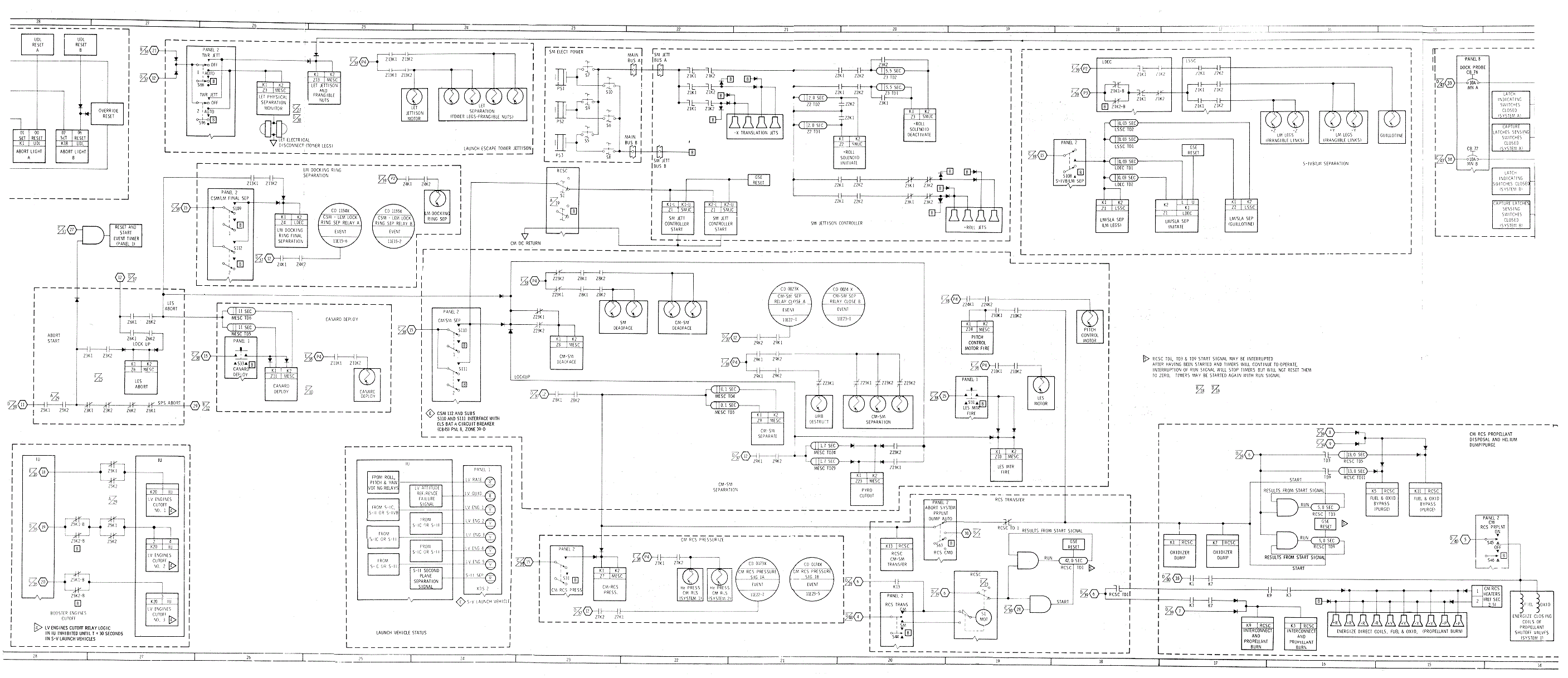
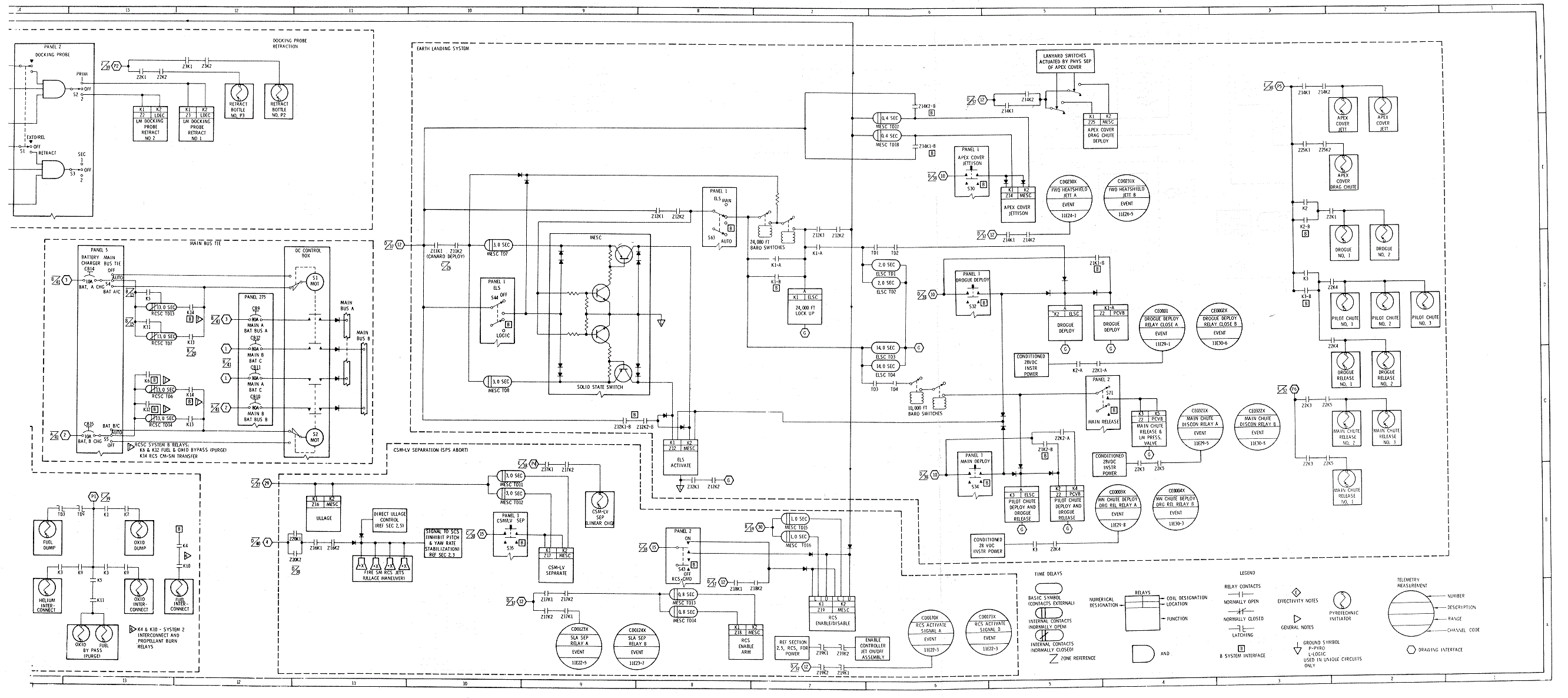
Sequential Systems Operational/Functional Diagram
Arming Sequential
Systems Logic Circuits
SIVB/LM Separation (Zone 39-F)
Main Parachute
Release (Zone 37-E)
EDS Bus Changeover.
(Zones 36, 37-A, and-B)
EDS Automatic Abort
Activation and Deactivation
Launch Vehicle Tank
Pressure Monitor
Launch Escape Tower
Physically Attached
Event Profile, Normal Ascent S-V LV
Angle
of Attack Monitor. (Zones 35 through 37-E and –F)
EDS Automatic Abort
Deactivate
Extinguish LIFT OFF
and NO AUTO ABORT Lights
Tower Separation
System Diagram
Separation of the
Spacecraft From the Launch Vehicle
Adapter Separation
System Diagram
Enable Automated
Control of the SM RCS
Event Profile,
Nominal Pre-Entry and Descent Diagram
Jettisoning the SM
(Zones 19 through 22-E and -F)
Deadfacing the
CM-SM Umbilical
CM-SM
Electrical Circuit Interrupter Diagram
CM-SM Umbilical
Assembly Diagram
Separation of the
CM From the SM
CM-SM Separation System Diagram
Earth Landing
System, Normal Sequence Diagram
Deployment of
Drogue Parachutes
Deployment of Main
Parachutes and Release of Drogues
Burning of the CM
RCS Propellants
Parachute Disconnect (Flower Pot) Diagram
Abort Start. (Zones
27 and 28-C and -D)
Event Profile, Mode
1A Abort Diagram
Event Profile, Mode
1B Abort T+42 Sec to 30,000 Feet
Event
Profile, Mode 1B Abort
˜̴ 30,000
Feet to 100,000 Feet Diagram
Event Profile, Mode
1C Abort Diagram
Event Profile, SPS Abort Diagram
Single
Bridgewire Apollo Standard Initiator Diagram
Compliance With
Design Requirements
Component Selection
and Installation
Thrust Vector Alignment of TJM
Thrust Vector
Alignment of LEM
Detonator Cartridge
Assembly Diagram
SLA Separation
Ordnance System
Pressure Cartridge
Assembly Diagram
Electrical Circuit
Interrupters
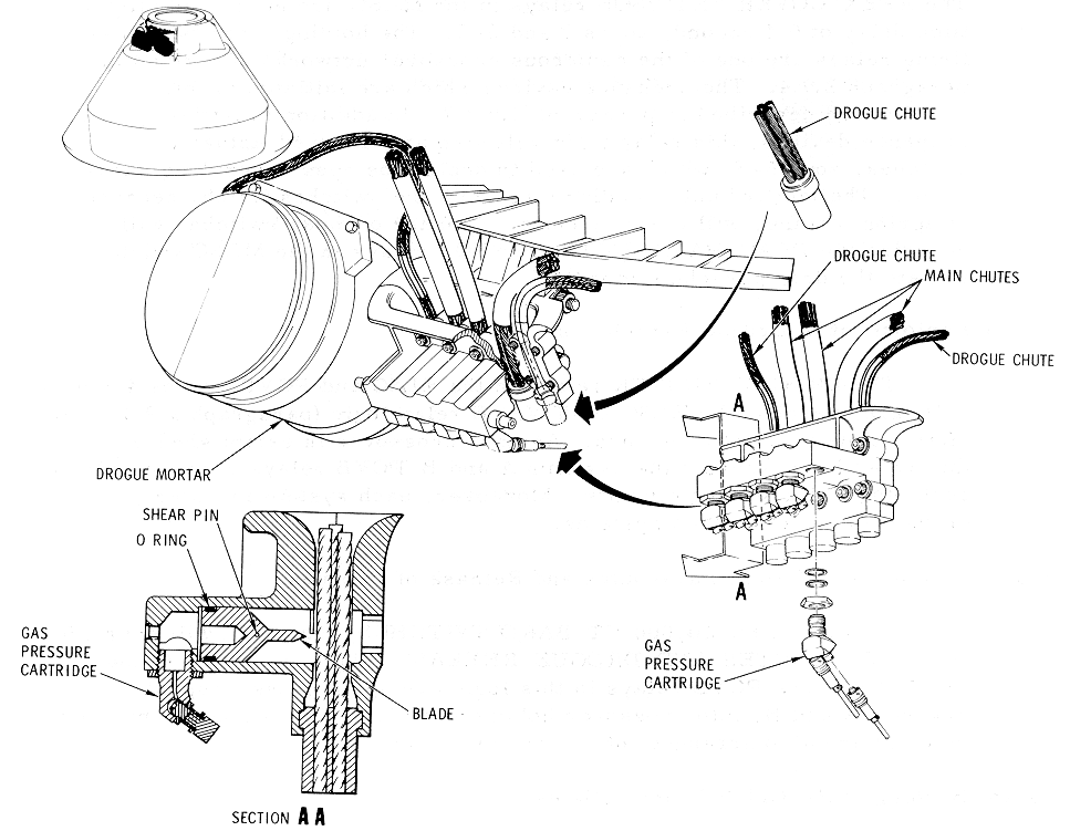
Parachute Mortar
Assemblies Diagram
OPERATIONAL
LIMITATIONS AND RESTRICTIONS
Alternate Selection
of Logic Power
Alternate Selection
of Pyro Power
Control for Arming
Pyro Systems
Status of Logic and Pyro Buses
Utilization of
Controls for CSM/LV Separation
Utilization of Controls for CM/SM Separation
Manual Control of
ELSC Functions
Sequential systems include certain detection and
control subsystems of the launch vehicle (LV) and the Apollo spacecraft
(SC). They are utilized during launch preparations, ascent, and entry
portions of a mission, preorbital aborts, early mission terminations,
docking maneuvers, and SC separation sequences. Requirements of the
sequential systems are achieve.cl by integrating several subsystems. The
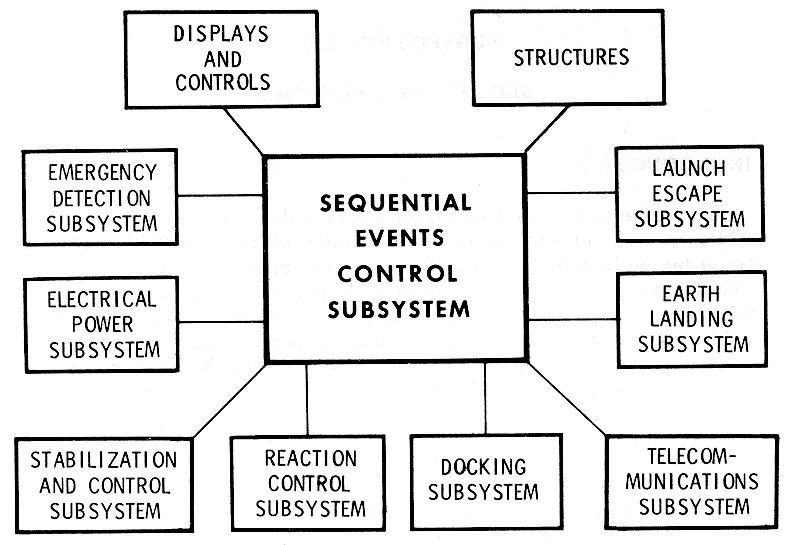
SECS Interface Diagram
illustrates the sequential events control subsystem (SECS)
which is the nucleus of sequential systems and its interface with the
following subsystems and structures:
•
Displays and controls
•
Emergency detection (EDS)
•
Electrical power (EPS)
•
Stabilization and control (SGS)
•
Reaction control (RCS)
•
Docking (DS)
•
Telecon1munications (T/C)
•
Earth landing (ELS)
•
Launch escape (LES)
•
Structural

Sequential Events Control Subsystem
The SECS is an integrated subsystem consisting of
twelve controllers which may be categorized in seven classifications
listed as follows:
•
Two master events sequence
controllers (MESC)
•
Two service module jettison
controllers (SMJC)
•
One reaction control system
controller (RCSC)
•
Two lunar module (LM) separation
sequence controllers (LSSC)
•
T wo lunar docking events
controllers (LDEC)
•
Two earth landing sequence
controllers (ELSC)
•
One pyro continuity verification
box (PC VB)
The relationship of these controllers and their sources
of electrical power are illustrated in the
SECS Controllers Diagrams.
Five batteries and three fuel cells are the source of electrical power.
The SMJC is powered by fuel cells; however, battery power is used for the
start signal. The RCSC is powered by the fuel cells and batteries. The
remaining controllers of the SECS are powered by batteries exclusively.

MESC, ELSC, LDEC, and PCVB Locations
Four controllers of the SECS are located in the
right-hand equipment bay (RHEB) of the CM. (MESC, ELSC, LDEC, and PCVB
Locations Diagram.)
MESC, ELSC, LDEC, and PCVB Locations Diagram

Installation of the redundant controllers on the
forward bulkhead of the SM in sector 2 is illustrated in
SMJC Location Diagram.
The fuel cells, which supply power for the SMJC, are also located in the
SM.

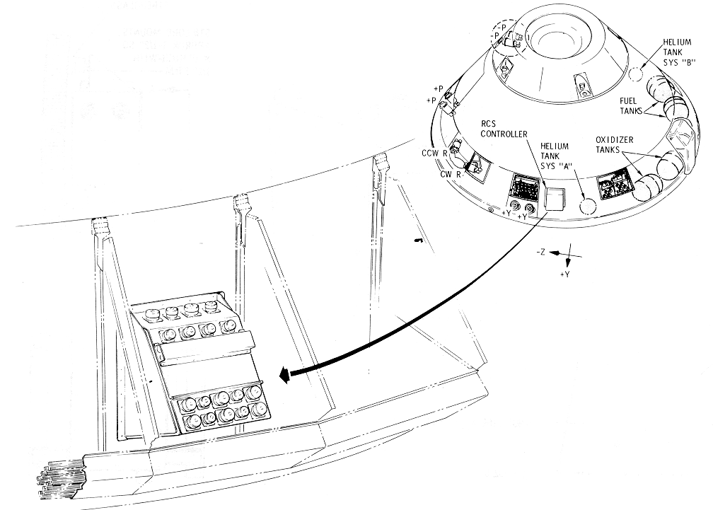
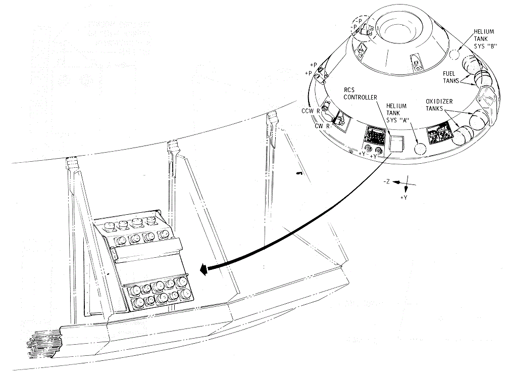
The location of the RCSC in the aft equipment bay of
the CM is illustrated in the
RCSC Location Diagram
.
Redundant controllers are located in the spacecraft LM
adapter (SLA) just forward of the LV instrumentation unit (IU); this
location is near the attachment point of the LM to the IU. For missions
that require dual launchings, the LSSC will be installed on the LV whicl1
is utilized to launch the LM. The LSSC
Location Diagram illustrates the location between the hinge
line of the SLA and the attachment plane of the IU.
The SECS receives manual and/or automatic signals and
performs control functions for normal mission events or aborts. The manual
signals are the result of manipulating switches on the main display
console (MDC) or rotating the Commander's translation hand control
counterclockwise, which is the prime control for a manual abort. Automatic
abort signals are relayed by the emergency detection system (EDS).
In several instances, normal mission events are
initiated manually with no provisions for automatic control. In other
instances, automatic control is provided with manual control included for
backup or override. In addition to the control functions, the sequential
systems incorporate visual display s which allow the flight crew to
monitor parameters associated with the LV.
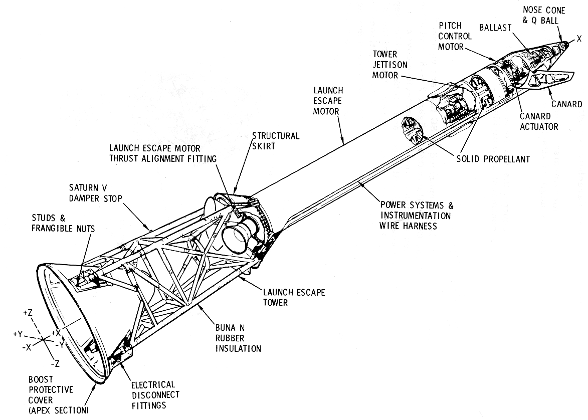
The apex section of the boost protective cover (BPC) (Launch
Escape Tower Assembly Diagram) is attached to the LET legs and
also to another section of the BPC which is described in Section 1,
Spacecraft. The LET is fabricated from welded titanium tubing which is
insulated against heat of rocket motor plumes. Two Saturn V dampers, one
of which cannot be illustrated in this perspective, interface with a tower
arm of the mobile launcher. Switches in the tower arm are tripped by the
dampers, and clamps are mechanized to secure the LET legs to prevent sway
caused by wind loads.
Launch Escape Tower
Assembly Diagram
Circuits of the SECS integrate the MESC, ELSC, and L
DEC providing manual and/ or automated controls for initiating ordnance
devices which are utilized in the following:
a.
Breaking frangible nuts which
retain the LET legs to the CM structure.
b.
Igniting the launch escape motor
(LEM), tower jettison motor (TJM), and pitch control motor (PCM) as
required for nominal mission or abort maneuvers.
c.
Deployment of the canards as
required to orient the launch escape vehicle (LEV) with the aft heat
shield forward during LES aborts. This orientation contributes to
efficient parachute deployment.
A Q-ball, which is a customer-furnished item,
interfaces with the sequential systems to monitor LV angle of attach: at
or near the MAX Q region during ascent.
Ballast is installed to control the CG location of the
LEV. The amount of ballast required is contingent on individual LEV weight
and balance data.
A passive tension tie is incorporated on SC that are
equipped with a docking probe. The tension tie is illustrated in the
Probe Passive Tension Tie
Diagram, and attaches the docking probe to the apex section of
the boost protective cover. During LES aborts the LET is automatically
jettisoned and ordnance which separates the docking ring from the CM is
initiated by relay logic of the MESC and LDEC; therefore, in this sequence
the docking probe is jettisoned with the LET because of the tension tie.
When the LET is jettisoned during a nominal ascent the docking ring
ordnance is not initiated and the tension tie is snapped from the docking
probe by thrust from the T JM.
Probe Passive
Tension Tie Diagram

On SC so equipped, docking probe retraction requires
pyro power from the SECS. Burst diaphragms are used to contain nitrogen in
four high- pressure cylinders which are included within the docking probe.
The nitrogen is used to retract the probe, and the diaphragms are ruptured
by plungers which are activated by ordnance devices. Mechanization and
control of the docking probe is included in Docking and Crew Transfer.
After transposition and docking, the crew will connect
the umbilicals which will mate the CM and the LM electrical circuits, in
Docking and Crew Transfer section. This electrical interface will enable
the utilization of the integrated LDEC and LSSC for S-IVB/LM separation.
The LM legs are secured to the SLA by clamps which are unlatched by
ordnance devices.
Separation of the CSM From the LV
When the command service module (CSM) is to be
separated from the LV either for nominal mission or abort requirements,
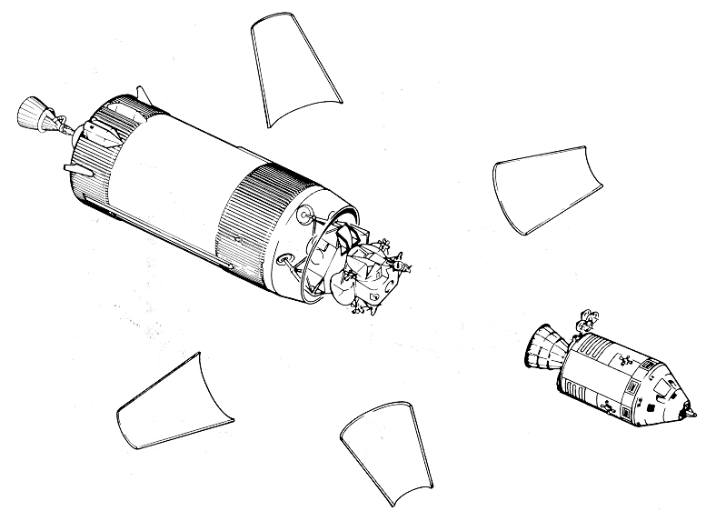
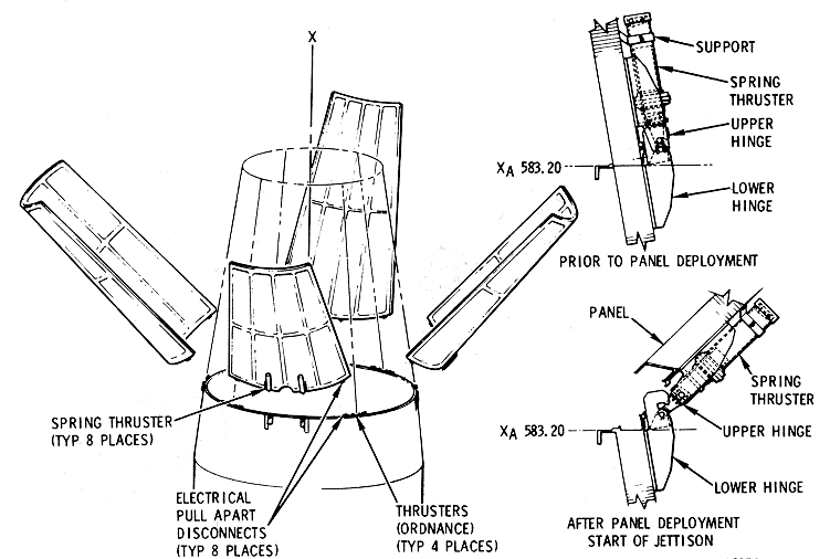
the MESC and LDEC are utilized (Normal CSM/LV Separation Diagram).
Manual controlled or automated circuits, whichever are utilized, will
initiate explosive trains that will sever and jettison the SLA panels (SLA
Panel Jettison Diagram).
Normal CSM/LV
Separation Diagram
CM-SM Separation and SM Jettison
Prior to the entry phase of a nominal mission, the MESC
and LDEC will be utilized to separate the CM from the SM and the SMJC will
automate jettisoning the SM (Normal CM-SM Separation and SM
Jettison Diagram).
Normal
CM-SM Separation and SM Jettison Diagram

Forward Heat Shield (Apex Cover)
Section 1 includes a description of the forward heat
shield structure; automated and manual controlled circuits for jettisoning
this heat shield are included in the integrated MESC, ELSC, and LDEC.
Mechanization of apex cover jettison is accomplished by the use of
thrusters and a drag parachute. The
Forward Heat Shield Attachment
and Thruster Assembly Diagram
illustrates pressure cartridges installed in a breech. When gas
pressure is generated by the pressure cartridges, two pistons will be
forced apart and a tension tie will be broken. The lower piston will be
forced against a stop and the upper piston will be forced out of its
cylinder. The piston rod ends are fastened to forward heat shield fittings
and the apex cover is forced away from the CM. Only two of the thruster
assemblies have breeches and pressure cartridges installed and plumbing
connects the breeches to thrusters mounted on diametrically opposite CM
structural members; this constitutes redundancy.
Forward
Heat Shield Attachment and Thruster Assembly Diagram

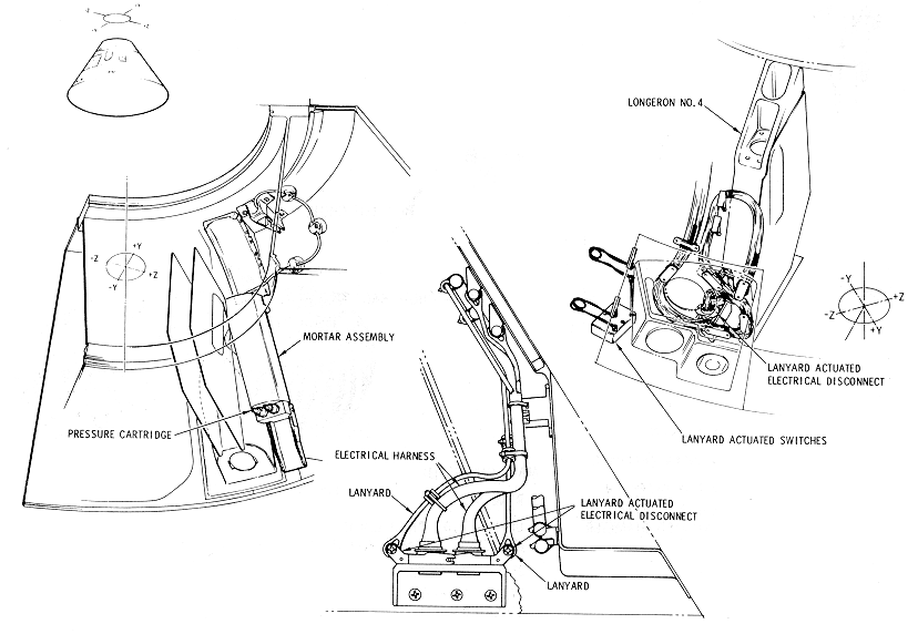
The Forward
Heat Shield Separation Augmentation System Diagram illustrates the
forward heat shield separation augmentation system. The mortar deployed
drag parachute, as the name implies, is used to drag the apex cover out of
an area of negative air pressure following the CM and will prevent
recontact of the apex cover with the CM. Lanyard-actuated switches are
used to initiate mortar pressure cartridges. A lanyard-actuated electrical
disconnect will deadface the electrical circuitry involved after the drag
parachute has been deployed.
Forward Heat Shield
Separation Augmentation System Diagram
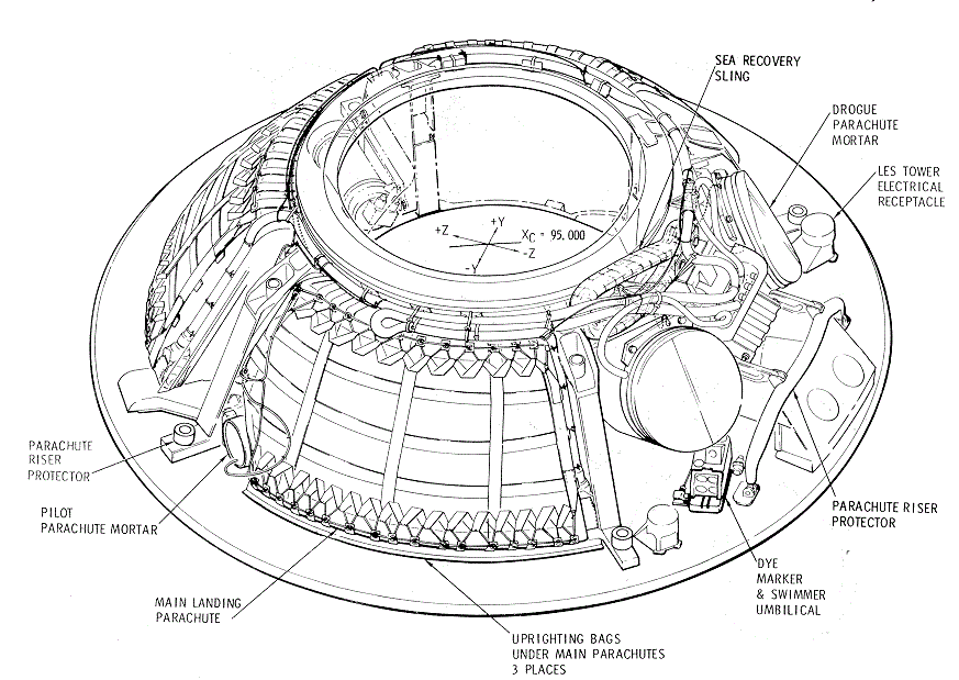
The apex cover must be jettisoned before the ELS
equipment may be utilized. The
ELS Equipment Diagram illustrates how the ELS
equipment is installed beneath the forward heat shield. All parachutes are
n1ortar-deployed to insure that they are ejected beyond boundary layers
and turbulent air around and following the CM. An RCS engine protector
prevents damage to CM RCS rocket engines by parachute risers. Parachute
risers are also protected from damage by parachute riser protectors, which
are spring-loaded covers over the LET attachment studs. The LES tower
electrical receptacles are used to connect LET interface wiring, and the
mating parts of the receptacles are pulled apart when the LET is
jettisoned. A sea recovery sling will be removed from stowage by member s
of the recovery team. Three uprighting flotation bags are installed under
the main parachutes. A switch is provided for the crew to deploy the sea
dye marker and swimmer umbilical any time after landing.
Eight parachutes are used in the ELS parachute system (ELS
Parachutes Diagram). The drogue and main parachutes are
deployed in a reefed condition to prevent damage from transient loads
during inflation. The ELSC will automate the deployment of these
parachutes when activated by relay logic in the MESC. Switches are
provided for the flight crew to disable the automation and deploy the
parachutes by direct manual control.

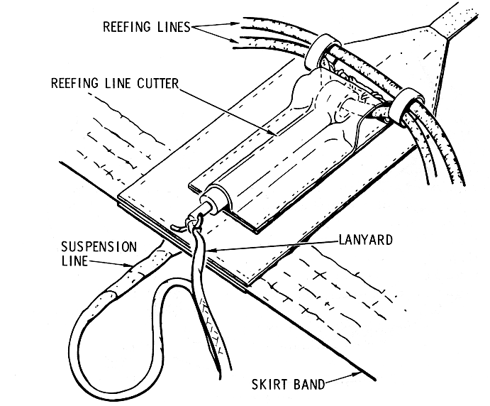
The drogue and main parachutes are reefed with lines
rove through reefing rings, which are sewn to the inside of the parachute
skirts and reefing line cutters (Reefing
Line Cutter Installation Diagram).
Reefing Line Cutter
Installation Diagram
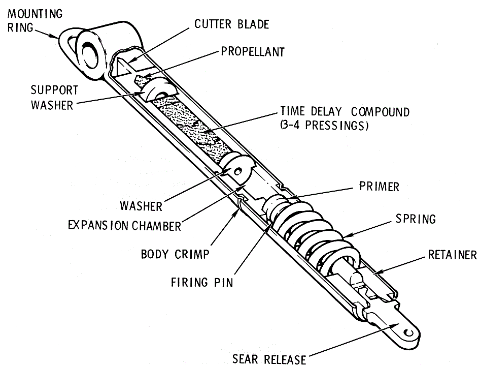
When the suspension lines stretch, a lanyard will pull
the sear release from the reefing line c utter, and burning of a
time-delay compound will be started (Reefing Line Cutter Diagram).
When the compound has burned, a propellant will be ignited and a cutter
will be driven through the reefing line.
Each of the drogue parachutes has two reefing lines
with two cutters per line to prevent disreefing in case any one reefing
line cutter should fail prematurely because a single reefing line cut in
one place will disreef a parachute. Each of the three main parachutes has
three reefing lines with two cutters per line. The time delay of four of
the cutters on each main parachute (two lines) is 6 seconds. At this time
the main parachutes will be allowed to open slightly wider than when
deployed. The time delay of the remaining two cutters on each main
parachute is 10 seconds. At this time the parachutes will be allowed to
inflate fully.
Reefing line cutters are also utilized in the
deployment of two very high frequency (VHF) antennas and one flashing
beacon light during descent. These recovery devices are retained by
spring-loaded devices which are secured with parachute rigging cord. The
cord is rove through reefing line cutters and the sear releases are pulled
by lanyards secured to the main parachute risers.
Dual redundancy with manual backup has been employed in
the design of the sequential system critical circuits. This ensures that
in all cases the effects of a component failure, in the prime failure
mode, will not:
a.
Prevent system operation when
required
b.
Cause inadvertent system
operation.
In most Apollo applications, premature operation of an
ordnance system is hazardous to the crew and could cause loss of mission
objectives. Identification and correction of single points of failure,
therefore, are prime objectives in the SECS circuit concept. Elimination
of single failures is accomplished by the addition of series contacts
(dual) in each fi ring circuit. The probability of premature operation of
an ordnance device has been greatly reduced by the utilization of series
elements. On the other hand, the reliability of the firing network to·
operate has been reduced. The overall firing circuit reliability is
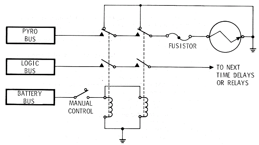
enhanced by the use of redundant firing circuits. E ach circuit is
independent of the other with each output controlling its own ordnance
component. Each of these redundant circuits is contained in independent
systems which are designated systems A and B. The Circuit Concept Schematic illustrates one of the
redundant systems of a typical firing network. This illustration also
shows that some control circuits for sequential events utilize the same
circuit concept.
Th e origin of signals and functions of the sequential
systems are illustrated in the
Sequential Systems Functional
Block Diagram. Launch escape system (LES) aborts may be
executed from the launch pad, or during a scent, until launch escape tower
(LET) jettison. Prior to lift-off, LES abort signals are initiated by
manual control only because the automatic abort circuits of the EDS are
activated at lift-off. Thereafter LES aborts may be initiated by manual
control or by automatic control during the period that the EDS automatic
abort circuits are active. LES aborts are categorized as modes 1A, 1B, and
1C aborts. Service propulsion system (SPS) aborts are categorized as modes
2, 3, and 4 aborts and may be initiated after the LET has been jettisoned.
No provisions are made to initiate SPS aborts automatically.
Sequential
Systems Functional Block Diagram

In addition to control for aborts, the sequential
systems provide for the monitoring of vital LV parameters and control for
other essential mission functions as follows:
a.
Sensing and displaying LV status:
1.
Thrust OK lights for all booster
engines
2.
Angular rates excessive
3.
IU guidance failure
4.
S-II stage second plane
separation (S- V launch vehicles only)
5.
LV propellant tank pressures
6.
Angle of attack.
b.
Receiving and displaying abort
requests from ground stations.
c.
Jettisoning of the LET:
1.
Initiate ordnance devices that
separate the LET from the CM
2.
Ignite T JM.
d.
Separation of the CSM from the
S-IVB stage:
1.
Enable controller reaction jet
on/ off assembly which provides automatic control of SM RCS engines.
·(Enable SM RCS/SGS. )
2.
Initiate ordnance devices that
separate the SLA:
(a)
Initiate cutting and deployment
of SLA panels
(b)
Separate SC/ LV umbilical
(c)
Separate LM/GSE umbilical.
e.
LM docking probe retraction on SC
so equipped.
f.
Separation of LM from S-IVB
stage: 1. Initiate ordnance devices that separate the LM legs from the SLA
2. Deadface LM pyro separation power 3. Initiate SLA/ LM umbilical
guillotine.
g.
Separation of the LM docking ring
on SC so equipped.
h.
Separation of the CM from the SM.
1.
Start SMJC:
(a)
Lock up fuel cell power to SMJC
(b)
Start -X jets of SM RCS
(c)
Start +roll jets of SM RCS
(d)
Stop +roll jets of SM RCS.
2.
Deadface CM-SM umbilical power.
3.
Pressurize CM RCS
4.
Transfer electrical power from SM
RCS engines to CM RCS engines and deadface SMJC start signal
5.
Transfer entry and postlanding
battery power to main d-c buses (main bus tie).
6.
Initiate separation ordnance
devices:
(a)
CM-SM tension ties
(b)
CM-SM umbilical guillotine
7.
Deadface CM-SM separation pyro
power (pyro cutout).
i.
Deployment of ELS parachutes:
1.
Activate ELSC
2.
Disable controller reaction jet
on/ off assembly which inhibits automatic control of CM RCS engines
(Disable CM RCS/SCS)
3.
Jettison apex cover
4.
Deployment of apex cover drag
parachute
5.
Deployment of drogue parachutes
6.
Release of drogue parachutes
7.
Deployment of pilot parachutes
-of the main parachutes.
j.
Deployment of recovery devices:
1.
Two VHF antennas
2.
One flashing beacon light.
k.
Burning of CM RCS propellants and
pressurant.
l.
Postlanding functions:
1.
Release of main parachutes.
The functions of a mode 1A abort are:
a.
Relay booster engine cutoff
(BECO) signal to the IU
b.
Reset and start the commander's
event timer
c.
Separation of the CM from the SM.
1.
Deadface CM-SM umbilical power
2.
Pressurize CM RCS
3.
Transfer electrical control from
SM RCS engines to CM RCS engines
4.
Transfer entry and postlanding
battery power to main d-c buses (main bus tie)
5.
Initiate separation ordnance
devices:
(a)
CM-SM tension ties
(b)
CM-SM umbilical guillotine.
6.
Fire LEM and PCM
7.
Start automated rapid propellant
dump (CM RCS propellant and pressurant jettison):
(a)
Initiate oxidizer dump
(b)
Initiate interconnect of A and B
fluid systems
(c)
Close propellant shutoff valves
(d)
Initiate fuel dump
(e)
Initiate helium dump (purge).
d.
Deploy canards
e.
Deployment of ELS parachutes:
1.
Activate ELSC
2.
Disable controller reaction jet
on/off assembly which inhibits automatic control of CM RCS engines
(Disable CM RCS/SCS)
3.
Jettison LET
4.
Separate LM docking ring on
spacecraft so equipped
5.
Jettison apex cover
6.
Deployment of apex cover drag
parachute
7.
Deployment of drogue parachutes
8.
Release of drogue parachutes
9.
Deployment of pilot parachutes of
the main parachutes.
f.
Deployment of recovery devices:
1.
Two VHF antennas
2.
One flashing beacon light.
g.
Postlanding functions: 1. Release
of main parachutes.
The functions of the modes 1B and 1C aborts are the
same as those for a mode 1A abort with the following exceptions;
a.
Firing of the PCM is inhibited
b.
Automated rapid propellant
jettisoning is inhibited. Propellants and pressurant of the CM RCS are
disposed of as in a nominal entry and landing procedure.
c.
Enable controller reaction jet
on/ off assembly which provides automatic control of CM RCS engines
(Enable CM RCS/SCS).
The functions of the sequential systems portion of an
SPS abort are;
a.
Relay BECO signal to the IU
b.
Reset and start commander's event
timer
c.
Initiate CSM direct ullage (+X
translation)
d.
Relay signal to SCS to inhibit
pitch and yaw rate stabilization
e.
Separate CSM from the LV:
1.
Initiate ordnance devices that
separate SLA:
(a)
Initiate severance and deployment
of SLA panels
(b)
Separate SC/ L V umbilical
(c)
Separate LM/GSE umbilical.
f.
Enable controller reaction jet
on/ off assembly which provides automatic control of SM RCS engines
(Enable SM RCS/SCS).
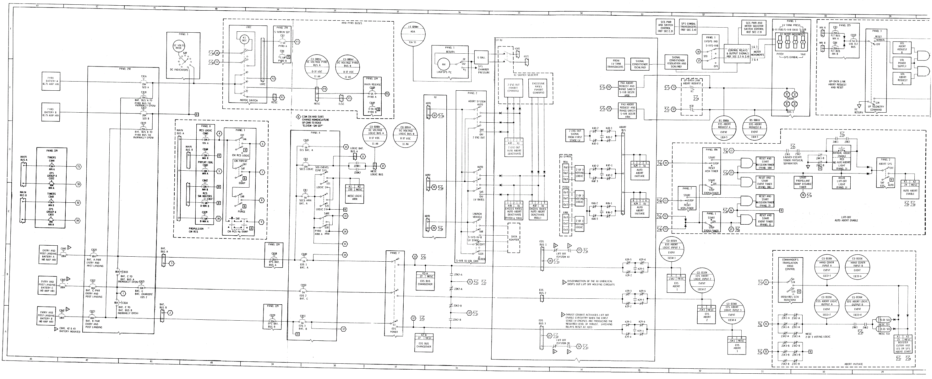
The
Sequential Systems Operational/Functional Diagram
illustrates the operation and functions of the integrated sequential
systems and zone references to this illustration are used in subsequent
paragraphs. This is an operational /functional diagram and should not be
misconstrued as an electrical schematic since many details of the
electrical system are not included, i.e., ground returns are not shown
except for the clarification of unique circuits. Also, initiator firing
circuits are not complete in the operational/functional diagram.
Circuit Concept Schematic illustrates that normally
closed contacts of firing relays are utilized to short the initiator to
ground and that all initiator firing circuits are protected with
fusistors. All initiators are grounded by relay logic and fusistors are
incorporated· even though the operational/functional diagram does not
illustrate this feature. Generally, only one of the redundant systems is
illustrated, which in this instance is system A; however, the redundant
system is included when the two are not identical. Numerous crossover
networks are illustrated where vital functions are concerned; in these
instances, systems A or B components will activate and/or initiate the
discrete requirements. Interface with other systems is limited to the
effect the interfacing system has on sequential systems.
Sequential
Systems Operational/Functional Diagram
Logic Power
(Zones 43- A and - B)
The source of logic power for the sequential systems is
entry and postlanding batteries A, Band C which are described in Electrical
Power Section. Utilization of the circuit breakers in these power
circuits is also described in the electrical power section.
Arming Sequential
Systems Logic Circuits (Zones 38
and 39-C and D)
Tl1ree circuit breakers are utilized in the system A
sequential systems logic arming circuits, and their counterparts (not
illustrated) are utilized in the system B circuits. The system A circuit
breakers are ELS BAT A (CB 45), SEQ EVENTS CONT SYS LOGIC A BAT A (CB 3),
and SEQ EVENTS CONT SYS ARM A BAT A (CB 1). The SEQ EVENTS CONT SYSTEM
LOGIC switches 1 and 2 (S11 and S15) are two pole lever- lock switches and
their function is SECS logic arming. When either of these switches is
closed, the MESC LOGIC ARM relays will be energized in systems A and B and
the MESC logic buses of both systems will be armed if the breakers of
systems A and B have been closed.
Pyro Power
(Zones 38 through43 - E and - F)
Normally the source of pyro power is pyro batteries A
and B; however, entry and postlanding batteries may be used as backup
sources of pyro power. Closure of SEQ A or B circuit breakers, (CB 16 or
17), zone 41 -E, will complete battery power circuits to pyro system A or
B. The condition of the pyro batteries may be determined by the use of a
d-c voltmeter (M10) and selector switch (S27), zones 40, 41-E, and -F. If
the voltage of either of the pyro batteries should be too low for crew
safety, entry battery power may be utilized. Opening the appropriate
PYRO/SEQ circuit breaker and closing the appropriate BAT BUS TO PYRO TIE
circuit breaker (CB 18 or 19), zones 41-D and -E, will execute the
selection, of backup power
Arming Pyro Buses
(Zones 38 and 39-E and -F)
The system A SECS pyro buses are armed with a motor
switch in the LDEC primarily for power conservation. When the motor is
driven to either position, power is not required to hold the switch
contacts in the selected position. The PYRO ARM s witch (S10), zone 38-C,
is used to control the LDEC motor switch (Kl), zones 39, 40-E, and -F.
Contacts of the motor switch control power to the LDEC, RCSC, and MESC
pyro buses. Pyro power for the ELSC is derived from the MESC pyro bus. ,
SIVB/
LM Separation (Zone
39-F)
Two circuit breakers are incorporated in the pyro power
systems that are required to separate the LM from the SIVB stage. When
mission requirements include this function, it will be necessary to close
the SIVB/ LM SEP, PYRO A, and/ or PYRO B circuit breakers (CB 3 or CB 4).
Main Parachute Release (Zone 37-E)
Two circuit breakers are incorporated in the pyro power
systems that are required to release the main parachutes from the CM. This
is a design change to eliminate the hazard of main parachute release
during descent. Closure of MAIN RELEASE, PYRO A and/ or PYRO B circuit
breakers (CB 48 or CB 49), should be accomplished as a postlanding
operation only.
EDS Bus Changeover. (Zones 36, 37-A, and-B)
Battery C provides an alternate power source for the
automatic initiation of an abort in the EDS and LET separation functions.
These circuits are normally powered by batteries A and B. This is
accomplished by the EDS bus changeover circuits in each MESC. Closure of
the EDS POWER switch (S1), zones 37-A and -B, energizes EDS CHANGEOVER
relays. When these relays are energized, battery A is coupled to system A
and battery B is coupled to system B. In the event of a power failure in
either system A or B, the relay logic will remove the existing battery and
couple battery C to the system which had a power failure.
The lift-off originated in the IU, zones 34 - A and -C,
is the result of two L/V events:
a.
Thrust commit activates lift-off
enable circuitry when the first stage LV engines are producing the
required level of thrust.
b.
Disconnection of the IU umbilical
will drop out lift-off holding circuits, which, in turn will switch the
lift-off signal power to the CSM. The umbilical will be disconnected at
the instant of actual lift-off.
If the appropriate circuit breakers and switches are in
the configuration intended for a nominal launch the lift-off signal will
initiate five events, zones 29 through 32-C and -D:
a.
Reset and start event and mission
timers (two each).
b.
Start the automatic PROPELLANT
DUMP AND PURGE DISABLE timer
c.
Illuminate the white LIFT OFF
light
d.
Provide power to illuminate the
red NO AUTO ABORT light in the event the MESC automatic abort circuits are
not enabled
e.
Enable the MESC automatic abort
circuits by energizing the AUTO ABORT ENABLE relays.
The LV EDS monitors critical parameters associated with
LV powered flight. Emergency conditions associated with these parameters
are displayed to the crew on the MDC to indicate necessity for abort
action. An additional provision of this system is the initiation of an
automatic abort in the event of certain extreme time critical conditions,
listed as follows:
a.
Loss of thrust on two or more
engines on the first stage of the LV.
b.
Excessive vehicle angular rates
in any of the pitch, yaw, or roll planes.
Concurrent with abort initiation (either manual or
automatic), the system provides BECO action except for the first 30
seconds of flight in the case of a S-V LV. Range safety requirements
impose the time restrictions.
EDS Automatic Abort Activation and Deactivation. (Zones 35 and 36-C through -E)
The EDS automatic abort circuits in the CSM are
activated automatically at lift-off and deactivated automatically at LET
jettison. Switches are provided on the MDC to deactivate the entire
automatic abort capability or the TWO ENGINES OUT and EXCESSIVE RA TES
portions of the system independently. Deactivation of the two automatic
abort parameters are also accomplished automatically in the IU just prior
to inboard engine cutoff (IECO) as a backup to the manual deactivation by
the flight crew.
The electrical circuits that provide illumination power
and control the LV status lights are in the IU. The LV RATE light, zones
24 and 25, will illuminate when LV roll, pitch, or yaw rates are in excess
of predetermined limits. To indicate· loss of attitude reference in the IU
guidance unit, the red LV GUID and the LV RATE lights illuminate during
first stage boost, then only LV GUID will illuminate. The yellow LV
ENGINES lights illuminate when a respective LV operating engine is
developing less than the required thrust output. The engine lights provide
four cues: (1) ignition, (2) cutoff, (3) engine below thrust, and (4)
physical stage separation. A red SII SEP light will illuminate at SII
first-plane separation and is extinguished at second.-place separation on
vehicles launched with an S-V booster. Each of these status lights has an
A and. B redundant circuit operation with separate lamps in each circuit.
Abort Request Light (Zone 31-E)
The ABORT light, is a red lamp assembly containing four
bulbs that provide high-intensity illumination. Two bulbs are in system A,
a n d two are in system B . The ABORT light is illuminated if an abort is
requested by launch control center for a pad abort or an abort during
lift-off via up-data link (UDL). The ABORT light can be illuminated after
lift-off by the range safety officer transmitting a DESTRUCT ARM COMMAND,
zone 33-E. An abort may also be requested via UDL from the manned space
flight network (MSFN). The ABORT lamps, systems A and/or B may be
extinguished by UDL reset commands; however, the flight crew can
extinguish the lamps in system B only with the UP TELEMETRY COMMAND switch
(S 39), zones 27 through 30-E and -F.
Launch Vehicle Tank Pressure Monitor
A time-shared display is used to indicate LV propellant
tank pressures and SPS gimbal position, zones 30 and 3 1-E and -F. The L
V/SPS IND selector s witch (S53), zone 32-F, is used to select the
parameters to be displayed. Meter movement selector switches and
operational power circuits are included in the STABILIZATION
AND CONTROL SYSTEM section.
The EDS will automatically initiate an abort signal
when two or more first stage engines are out, zone 34-D, or when L\T
excessive rates are sensed by gyros in the IU, zones 34-C and -D. These
abort signals will energize an ABORT BUS which will energize AUTO ABORT
INITIATE relays, zones 33-C and -D. When the AUTO ABORT INITIATE relays in
the IU are energized, the auto abort voting relays in the MESC are
deenergized,
MESC Auto Abort Voting Logic. Three matrices of relay
contacts, each of which constitutes 2 of 3 voting logic, are in the abort
signals to the ABORT BUS and the function s of these relays are automatic
abort deactivate, EDS
Automatic Abort Activation and Deactivation, zones 34-C and
-D. The source of power to energize the AUTO ABORT DEACTIVATE relays is in
the IU, zones 36-C, -D and -E, and may be controlled by switches in the
CM. If the 2 ENG OUT switch (S64), zone 36-E, is placed in the OFF
position, the 2 ENG OUT AUTO ABORT DEACTIVATE relays will be energized and
the 2 engines out signal from the first stage will be inhibited from
initiating an automatic abort. If the LV RATES switch (S65), zone 36-D, is
placed in the OFF position, the EXCESSIVE RATES AUTO ABORT DEACTIVATE
relays will be energized and the abort signals from the IU gyros will be
inhibited from initiating an automatic abort.
When the EDS bus changeover circuits are energized (EDS
Bus Changeover. (Zones 36, 37-A, and-B)), three hot wire loops
are established between the CM and LV. Power from the EDS buses l, 2, and
3 energize the EDS ABORT relays 1, 2, and 3 in the MESC, zones 31 and 32-A
and - B. The three legs of E DS bus power are through three matrices of
relay contacts of the AUTO ABORT INITIATE relays (LV Auto Abort Logic),
zones 33-A through -D. When an automatic abort is initiated in the IU the
EDS ABORT relays in the MESC are de-energized, this constitutes three
abort votes in the MESC. The MESC A 2 of 3 voting logic is illustrated
with matrices of EDS ABORT relay contacts, zones 30 and 31-A. The
automatic abort signal through this voting logic is described in Aborts
Launch Escape Tower Physically Attached
One of the requirements for the automatic abort
circuits to be enabled is to have the LET physically attached to the CM (Launch
Escape Tower Assembly Diagram). Another requirement is logic
power to the circuits associated with tower attachment. The power may be
from the EDS bus changeover circuits (EDS Automatic Abort Activation
and Deactivation) or from the MESC LOGIC bus (Arming Sequential Systems Logic
Circuits). The LET PHYSICAL SEPARATION M0NITOR relays, zone
25-F, have ground wires routed through the tower legs. One pair of
contacts of these relays is in the holding circuit to the AUTO ABORT
ENABLE relays (Auto
Abort Enable), zone 31-D. An automatic abort is impossible
after the tower has been jettisoned because the AUTO ABORT ENABLE relays
will have been de-energized.
The last requirement for an abort initiate signal to be
automated is to have the MESC automatic abort circuits enabled. If the EDS
switch (S67), zone 29-D, is in the AUTO position, a lift-off signal (Lift-Off) from the IU
will enable these circuits. Relay logic in the automatic abort enable
circuits are designed to establish holding circuits on battery bus power.
These holding circuits are required to maintain the automatic abort
circuits in an enabled state since the lift-off signals are discontinued
from the IU at IECO. For the holding circuits to be established, power
must be made available from the SECS LOGIC CB3 (Arming Sequential Systems Logic
Circuits), and the LET must be physically attached and
electrically mated (Launch
Escape Tower Physically Attached). Normally closed contacts of
the system B AUTO ABORT ENABLE relays are installed in the negative return
of the red NO AUTO ABORT light. Therefore, when the automatic abort
circuits are enabled, the red NO AUTO ABORT light will not be illuminated.
The LIFT OFF and NO AUTO ABORT lights are combined in an illuminated
pushbutton (IPB) which is the only illuminated switch in this group.
Illumination of the red light would be tl1e indication that complete
enabling of both systems had not been established. If the white LIFT OFF
light should not illuminate at lift-off, the most probable cause would be
a failure of both lift- off signals in the IU. In this event, the IPB
should be depressed momentarily to allow the automatic abort circuits to
be enabled from the alternate battery bus power source; neither of the
lights would be illuminated in this instance.
The
Event Profile, Normal Ascent S-V LV illustrates the
normal ascent for S-V launch vehicles.
Event Profile,
Normal Ascent S-V LV Diagram
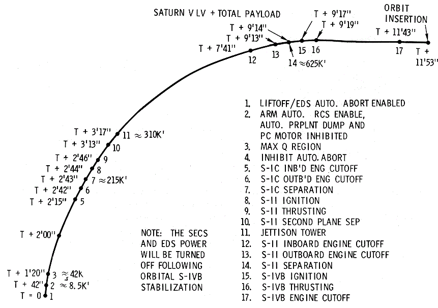
At + 42 seconds, the ABORT SYSTEM PRPLNT switch (S63), zone 20-B, will be changed from the DUMP AUTO position to the RCS CMD position. The DUMP AUTO contacts of the switch are in series with contacts of the PROPELLANT DUMP AND PURGE DISABLE timer which was started at lift-off (Lift-Off). Additional information relative to this time delay and procedural switching is included in the RCS section, RCS.
Angle of Attack Monitor. (Zones 35 through 37-E and -F)
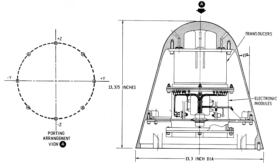
A Q-ball (EDS
Q Ball Diagram) mounted above the LES motors,
provides an electrical signal input to the LV AOA/SPS Pc indicator and an
electrical signal input to ground control via telemetry. The Q-ball has
eight static ports for measuring ΔP
which is a function of angle of attack. The pitch and yaw ΔP
signals are electronically vector-summed in the Q-ball and displayed on
the indicator. The indicator is monitored for the LV AOA function during
ascent when the LV is at or near the max Q region. This is a time-shared
instrument with the service propulsion system (SPS), and the 150-percent
graduation is because of SPS start transients. Use of the scale during the
LV AOA period will be as a trend indicator only with abort limits
established in mission rules.
EDS Automatic Abort Deactivate
The entire automatic abort capability or a portion of
the circuits may be deactivated by the flight crew prior to staging (EDS Automatic Abort Activation
and Deactivation). If the EDS switch (S67), zone 29-D, is
switched to the OFF position, the entire EDS automatic abort capability
will be deactivated (Auto
Abort Enable). If the 2 ENG OUT switch (S64) and/or LV RATES
switch (S65) are switched to the OFF position, the appropriate automatic
abort parameter will be deactivated (LV
Auto Abort Logic). Automated switching in the IU SWITCH
SELECTOR, zone 35-E, will also deactivate the two automatic parameters as
a part of the staging sequence.
Extinguish LIFT OFF and NO AUTO ABORT Lights
Just before IECO, the LIFT OFF ENABLE INHIBIT relay
contacts in the IU are opened, zones 34-A and -C. This interrupts EDS bus
power which is required to illuminate the lamps of the LIFT OFF and NO
AUTO ABORT displays; If the EDS switch (S67) is used to deactivate the EDS
automatic abort circuits (EDS
Automatic Abort Deactivate), the NO AUTO ABORT lamps will have
been illuminated and will be extinguished at this time. When the EDS bus
power is interrupted by this IU relay logic, the mission and event timers,
which were started at lift-off, will continue to operate because of
internal holding circuits in these units.
After staging, the LET is jettisoned (Normal Tower Jettison Diagram).
Normally, both of the TWR JETT switches (S66 and S96), zone 26-F, will be
used to initiate this function; however, either one of the switches will
initiate systems A and B tower jettison circuits. Each of these switches,
No. 1 and 2, are double pole switches and system A logic or EDS changeover
power will enable one of the poles of each switch. Moreover, one pole of
each switch will activate the circuits of system A and the other pole
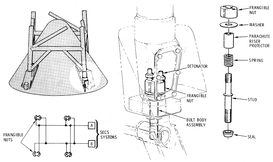
system B. The frangible nuts which attach the tower legs to the CM are
illustrated in the Tower
Separation System Diagram. Each nut assembly includes two
detonators, one initiated by system A circuits, and the other by system B.
The tower jettison circuits will also ignite the TJM. The cue which the
flight crew will use when initiating LET jettison is the S- 11 SEP light.
Utilization of the event timer in conjunction with the visual light cue
will enable the crew to jettison the LET at the correct time. If the TJM
should fail to ignite, an alternate method may be used to jettison the
LET. The LES MOTOR FIRE switch (S31), zone 19- C, will ignite the LEM
which is flight-qualified to jettison the LET. If this alternative should
be necessary, it is vital that the detonators of the frangible nuts shall
have been initiated before the LES MOTOR FIRE switch is depressed. Th e
TWR JETT switches are the only controls that will initiate the detonator s
of the frangible nuts.
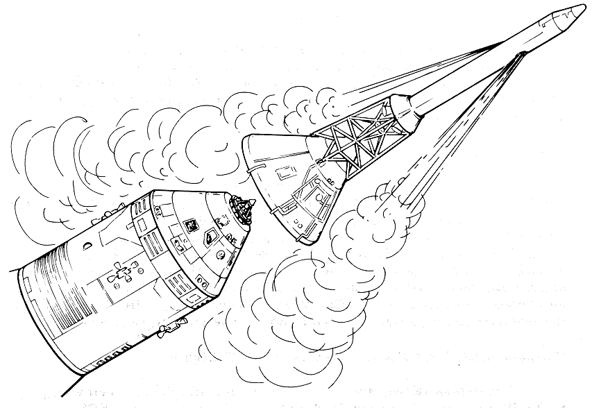
Tower Separation
System Diagram
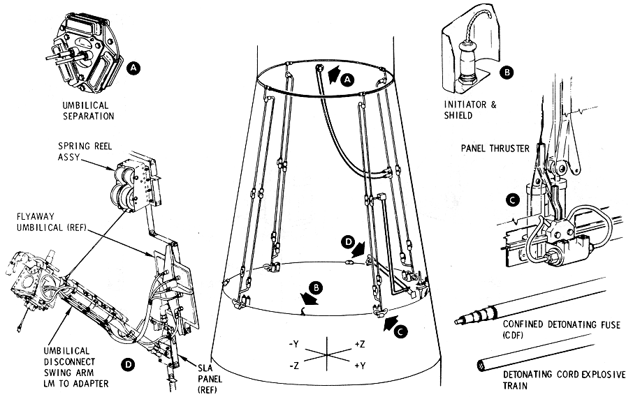
Separation of the Spacecraft From the Launch Vehicle
The next maneuver that the sequential systems will be
utilized to perform is CSM/LV separation (Adapter Separation System Diagram).
Closing the CSM/LV SEP switch (S35), zone 10-B, will energize the CSM/LV
SEPARATE relays, which will fire initiators of the explosive trains that
sever and jettison the SLA panels . The same explosive train will separate
the CSM/LV and LM/GSE umbilicals.
Adapter Separation
System Diagram
Enable Automated Control of the SM RCS
The CSM-LV SEPARATE relay will, in addition to
initiating the explosive train, energize the RCS ENABLE ARM relays, zone
8-A, which, in turn, will energize the latching coils of the RCS ENABLE
relays, zone 7-A. This relay logic will enable the controller reaction jet
on/off assembly which couples the SCS jet selection logic and SM RCS, RCS
section.
This system is designed for two retractions with backup
for each. Since there are four retraction cylinders, however, four
retractions are possible under ideal circumstances.
The DOCK PROBE RETRACT PRIM and/or SEC switches (S2 and
S3), zones 13-E and -F, are armed when four conditions are satisfied.
These are:
a.
The appropriate buses are
energized and the appropriate circuit breakers are closed, zones 15-E and
-F.
b.
The EXTEND/REL switch (S1), zones
14-E and -F, is in the RETRACT position.
c.
The latch indicating switches in
the docking ring latches are closed (system A and/ or B as required).
d.
The capture latches sensing
switches are closed (probe head latched in LM drogue).
When these conditions are satisfied, the DOCK PROBE
RETRACT switches may be utilized to energize the L M DOCKING PROBE RETRACT
No. 1 and 2 relays as required. Contacts of these relays will fire the
initiators and retraction will be executed.
Pyro power circuits to the LSSC include a circuit
breaker which is described in
SIVB/LM Separation (Zone 39-F). The S-IVB /LM SEP
PYRO A circuit breaker (CB3), zone 39-F, must be closed to complete the
system A LSSC pyro circuit. The LDEC is also required in this automation.
Closing the S-IVB/LM SEP switch (Sl08), zone 18-E, will
start the following sequence:
a.
The LM/SLA SEP (LM LEGS) relays
of the LSSC, will be energized and their contacts-will fire the initiators
of the frangible links which retain the LM legs.
b.
The nonlatching relay and the
latching coils of the latching relay of the LM/SLA SEP INITIATE relays in
the LSSC will be energized after a time delay of 30 milliseconds.
c.
The LM/SLA SEP (GUILLOTINE)
relays of the LSSC, will be energized after a time delay of 30
milliseconds.
Contacts of the LM/SLA SEP INITIATE relays will
deadface LSSC pyro power which was utilized to fire the frangible links of
the LM legs. Contacts of the system B LM/SLA SEP INITIATE relays are in
the system A deadfacing circuits for series/parallel redundancy; system A
contacts are utilized in system B (not illustrated) for the same reason.
LDEC pyro power fires the umbilical guillotine through
contacts of the LM/SLA SEP INITIATE relays in the LDEC and the LM/SLA SEP
(GUILLOTINE) relays in the LSSC. Deadfacing of LDEC pyro power is
accomplished when the switch is allowed to return to its maintain position
and the relay coils are de-energized. The contacts of the nonlatching
relays will return to their initial state but the contacts of the latching
relay will not revert to their initial positions.
Logic power through the momentary contacts of either of
the CSM/LM FINAL SEP switches (S109 or S112), zone 26-D, will energize the
LM DOCKING RING FINAL SEPARATION relays in the LDEC. These are the firing
relays for the ordnance which severs the docking ring from the CM tunnel.
Arming the SECS is the first requirement of the
sequential systems preparatory to a nominal entry and descent (Logic Power and Pyro Power). If mission
rules require a checkout of the CM RCS prior to CM/SM separation, it is
vital that electrical control of the RCS be placed in the SM RCS
configuration prior to initiating the separation (Jettisoning the SM (Zones 19
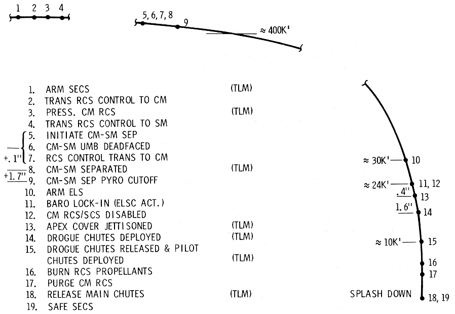
through 22-E and -F)). The
Event Profile, Nominal Pre-Entry
and Descent Diagram illustrates a nominal pre-entry and
descent profile.
Event Profile,
Nominal Pre-Entry and Descent Diagram
When either of the CM/SM SEP switches (S110 or S111),
zones 24-C and -D are closed, logic power will start the automated
sequence of CM/SM separation. Each of these switches, No. 1 and 2, is a
doublepole switch with one pole controlling system A components and the
other pole controlling system B components. When either or both of these
switches are utilized for CM/SM separation, they should be held closed for
approximately 0.1 of a second to allow the time-delay relay logic to
function properly (Pyro
Cutout).
Jettisoning the SM (Zones 19 through 22-E and -F)
A manually initiated CM/SM separation signal will start
the SMJC with logic battery power through contacts of the RCSC motor
switch (S1), z one 23-E. The motor switch must be in the SM control
position for the start signal to activate the SMJC (Nominal Pre-entry and Descent).
Latching relays are utilized to couple fuel cell electrical power to the
SMJC and to energize the manual coils of the SM RCS-X engines. Fuel cell
power to the SMJC is through contacts of motor switches, zones 23-E and
-F, which are described in Electrical
Power Section. The control circuits in the SMJC constitute a
crossover network; either system A or B will energize the manual coils of
both of the SM RCS redundant engine systems. The +roll engines will be
started 2.0 seconds after the SMJC is started and will operate f or 5.5
seconds. The -X translation engines will continue to burn until the
propellants are depleted or the fuel cells are expended, whichever occurs
first.
Deadfacing the CM-SM Umbilical
Closure of either of the CM/SM SEP switches will
energize the CM/SM DEAD FACE relays to the MESC, zone 23-C. These relays
are utilized to initiate the ordnance devices of the CM-SM electrical
circuit interrupter (CM-SM Electrical Circuit
Interrupter Diagram) and the SM circuit interrupter (CM-SM Umbilical Assembly Diagram).
These relays may be considered as pilot relays to the automation of other
CM-SM separation functions which includes interface with the CM-RCS.
CM-SM
Electrical Circuit Interrupter Diagram
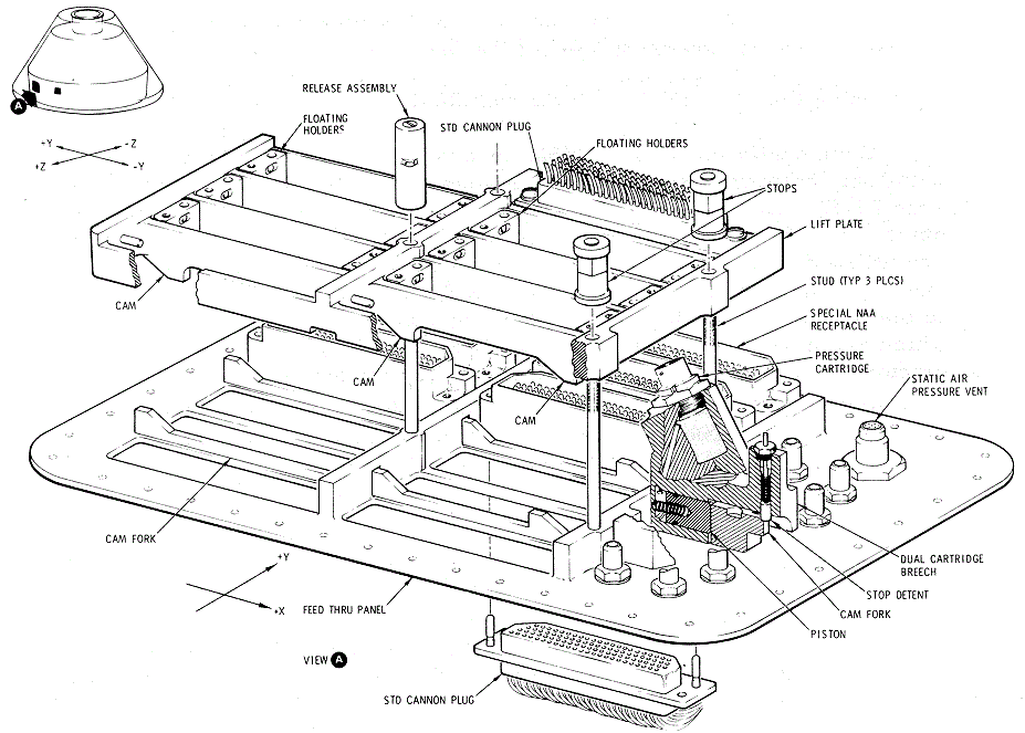
CM-SM Umbilical
Assembly Diagram
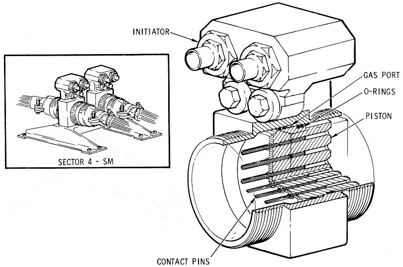
Separation of the CM From the SM
When the CM-SM SEPARATE relays in the MESC are
energized after a time delay of 0.1 second, ordnance devices required for
CM-SM separation are initiated. These are the guillotine blades of the
CM-SM umbilical assembly (CM-SM
Umbilical Assembly Diagram) and three tension ties between the
CM and SM structures (CM-SM
Separation System Diagram). The time delay is
required in this circuit so that the guillotine blades will cut wires
which were deadfaced (Deadfacing
the CM-SM Umbilical).
CM-SM Separation
System Diagram
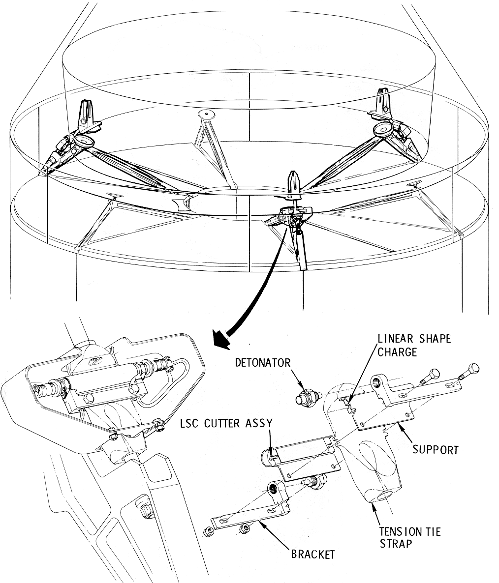
The pyro cutout circuits are incorporated to eliminate
the possibility of draining pyro power through wiring which may have one
or two strands shorted by umbilical blades, or any other high resistance
short. Fusis tors afford protection against "dead shorts" (Circuit Concept and
OPERATIONAL DESCRIPTION).
The PYRO CUTOUT relays, zone 20- B, are energized 1. 7 seconds after the
CM-SM SEPARATE relays. Contacts of the PYRO CUTOUT relays are in the logic
circuits to the CM-SM DEADFACE relays, zone 23-D. Contacts of the PYRO
CUTOUT relays are also in the pyro circuits to the initiators that are
expended in the separation sequence, zones 20 through 23-C and -D. This
relay logic is an arc suppression system since electrical energy is
removed from initiator firing relay contacts at the time they return to
their normal state. When the CM/SM SEP switch is released it will return
to its normally open state and all relays in this logic, including the
PYRO CUTOUT relays, will be de-energized.
Any time a CM-SM separation signal is initiated in the
MESC, a signal is automated for the initiation of two CM RCS functions.
These are:
a.
Fluid systems pressurization,
zones 21 through 23-A and -B. The system 1 CM-RCS PRESS relay logic
provides firing circuits to one of the HELIUM SQUIB ISOLATION valves in
each of the redundant fluid systems of the CM RCS system.
b.
Transfer electrical control from
the SM RCS to the CM RCS, zones 18 through 20-A and -B. RCS CM-SM TRANSFER
relay logic in the RCSC will drive the transfer motor switch to the SM
position. Moreover, contacts of the motor switch are utilized to deadface
the SMJC start signal, zone 23-E. There is a time delay of approximately
.50 milliseconds in this deadfacing function which is explained as the
time it takes the motor switch contacts to change state.
Relay logic of the RCSC, zones 11 through 13-C and -D,
will couple ENTRY A ND POSTLANDING batteries A, B and C to the main buses
providing certain circuit breakers and switches of the electrical
power system are in the correct position for this automation.
Closure of the ELS LOGIC switch (S44), zone 10-D, will
complete logic power circuits to redundant transistorized switches in the
MESC. These solid state switches function as a pair of AND gates, each of
which requires two inputs to emit. One of the inputs is satisfied when the
logic power circuits are completed.
Logic power circuits to the ELSC, including ground
returns for the components in this controller, are not completed until the
ELSC ACTIVATE relays in the MESC are energized, zone 8-C. The solid state
switches (Arm
ELSC) control the logic power required to energize these
relays. Assuming that the ELS switch (S63), zone 8-E, is in the AUTO
position, closure of the 24,000 FT BARO SWITCHES will satisfy the second
input to the solid state switches. Logic power in this instance is derived
from a point between the ELS LOGIC switch and the solid state switches. It
is wired, through a resistor, to a point between the redundant baro
switches. Both baro switches will be closed at the same time and the
reduced logic power because of the resistor, will be sufficient to trigger
the solid state switches; however, the reduced logic power is not
sufficient to energize relay coils of the ELSC. When the ELSC ACTIVATE
relays are energized, another crossover network is established; system B
relay logic will establish holding circuits to the system A relays;
moreover, system B relay logic can energize system A relays.
In addition to activating the ELSC (Activate ELSC), closure
of the 24,000 FT BARO SWITCHES will energize the 24,000 FT LOCK UP relay
in the ELSC, zone 7 -D. This relay logic, together with the system B
counterpart, will establish logic power holding circuits which bypass the
24,000 FT BARO SWITCHES.
A signal is relayed to the unlatching (disable) coils
of the R CS/ SCS ENABLE relay, zone 7- A, when the ELSC is activated (Arm ELSC). This relay
logic disables the controller reaction jet on/off assembly (RCS Section).
When the ELSC has been activated (Activate ELSC), the first
function that will be automated is apex cover jettison (Earth Landing System, Normal
Sequence Diagram).
Earth Landing
System, Normal Sequence Diagram
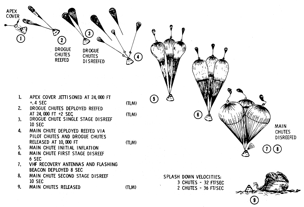
The APEX COVER JETTISON relays in the MESC are
energized after a time delay of O .4 second, zones 5 and 6-E. The holding
circuits of these firing relays are one of the numerous crossover networks
described in paragraph OPERATIONAL
DESCRIPTION. The ordnance devices which are initiated in this
function are described in paragraph Forward Heat Shield (Apex Cover).
In addition to initiating the ordnance devices, this relay logic will also
arm lanyard-actuated switches, zone 5-F, which are used to deploy the apex
cover drag parachute. The lanyard pulls holding pins from the switches
which, because of spring loading, will close circuits. Closure of these
switches will energize the DRAG PARACHUTE DEPLOY relays in the MESC which
initiate the drag parachute mortar.
Deployment of Drogue Parachutes
The DROGUE IGNITER relays in the ELSC and PCVB, zones 4
and 5-D, are energized by ELSC ACTIVATE relay logic (Activate ELSC) after a
time delay of 2 seconds. Another crossover is established in this relay
logic wherein the systems A and B PCVB relays cross-couple each other with
holding circuits. Moreover, each system initiates ordnance devices of both
systems.
Deployment of Main Parachutes and Release of Drogues
Closure of the 10, 000 F T BARO SWITCHES, zone 6-C,
will energize the PILOT CHUTES AND DROGUE RELEASE relays in the ELSC and
the PCVB. The PCVB relays in this logic are again cross-coupled, systems A
and B, into crossover holding circuits. The ordnance initiator circuits
are also arranged into a crossover network.
Burning of the CM RCS Propellants
Switches in the CM RCS, zones 40-C and -D, are used to
energize the direct coils of ten CM RCS jets, zones 15 and 16-A. The
correct utilization of these switches is described in the RCS
Section.
Closure of the MAIN.RELEASE switch
(S71), zones 4 and 5-C, will energize the MAIN CHUTE RELEASE relays in
the PC VB. These relays are used to initiate ordnance which will drive
cutter chisels through the main parachute risers (Parachute
Disconnect (Flower Pot) Diagram).
Parachute
Disconnect (Flower Pot) Diagram
Abort signals may be initiated manually by rotating the
commander's translation hand control counterclockwise into a de tent. Two
cam-operated micro switches, zone 31-B, are included in the control. Batt.
power through these switches will energize the BOOSTER CUTOFF AND LES OR
SPS ABORT START RELAYS in the MESC, zone 29-A.
These relays may also be energized by an EDS automatic
abort signal (MESC
Auto Abort Voting Logic) through 30-millisecond time delays.
The reason for the time delays is to insure against spurious signals
initiating an abort. EDS bus changeover power (EDS Bus Changeover. (Zones 36,
37-A, and-B)) is utilized to energize the BOOSTER CUTOFF AND
LES OR SPS ABORT START relays in the event of an EDS automatic abort. Any
ab ort signal will automate two functions which are common to all abort
sequences. These are:
a.
BECO, zones 27 and 28-A and -B,
is inhibited by IU relay logic until T + 30 seconds in the S-V LV
configuration because of range safety requirements.
b.
Reset and start the commander's
event timer, zone 27-D. It is necessary for the EVENT TIMER START switch
(S5 6), zone 32-C, to be in the CENTER ON position for this function to be
automated.
Abort Start. (Zones 27 and 28-C and -D)
Two pairs of LET PHYSICAL SEPARATION MONITOR relay
contacts (Launch
Escape Tower Physically Attached) are in the abort start relay
logic. One pair is normally closed and the other is normally open. The
state of these contacts at the time an abort is initiated will determine
whether an LES or SPS abort is automated in the sequential systems. When
the BOOSTER CUTOFF AND LES OR SPS ABORT START relays are energized (Aborts), the LES ABORT
relays may or may not be energized; if they are energized, an LES abort
will be started if not, an SPS abort will be started.
Initially the sequential events of all LES aborts are
identical. In addition to the functions that are common to all aborts (Aborts),
separation of the CM from the SM is automated. The automated CM/SM
separation sequence is the same as the manually initiated separation
sequence described under nominal pre-entry, entry, and descent (Nominal Pre-entry and Descent)
with two exceptions which are:
a.
The SMJC is not started when the
separation sequence is started by a LES abort signal, zone 24- D.
b.
In an LES ABORT the CM/SM
separation sequence includes the firing of the LEM, zones 14 through 21 -
C.
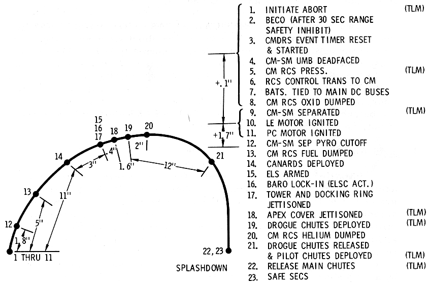
A mode 1A abort (Event Profile, Mode 1A Abort
Diagram) is initiated prior to the expiration of the
PROPELLANT DUMP AND PURGE DISABLE TIMER (TDl) in the RCSC, zone 18-B. This
time-delay relay logic is started.at lift- off (Lift-Off)
providing two conditions are satisfied. These are :
a.
The RCSC motor switch (S1), zone
19-A, must be in the SM RCS control position (as illustrated).
b.
The CM RCS LOGIC switch (S46),
zone 40- D, must be in the CM RCS LOGIC position.
Event Profile, Mode
1A Abort Diagram
A pair of latching contacts, which are closed when the
timer is reset by GSE, are in series with the PRPLNT DUMP AUTO contacts of
the ABORT SYSTEM PRPLNT switch (S63), zone 20-B. When this switch is in
the PRPLNT DUMP AUTO position, and before the timer contacts are opened,
the requirements peculiar to a mode 1A abort may be automated. These are:
a.
The PCM is fired by the same
relay logic that ignites the LEM, zone 19-D. Logic power for energizing
the PCM firing relays is derived through the closed contacts of the
PROPELLANT DUMP AND PURGE DISABLE timer, zone 19-B.
b.
The OXIDIZER DUMP RELAYS, zone
17-B, are energized immediately with an abort initiate signal resulting in
four CM RCS functions:
(1)
closure of the PROPELLANT SHUTOFF
valves, zone 14-A;
(2)
energization of the INTERCONNECT
AND PROPELLANT BURN relays, zones 16 and 17-A;
(3)
initiation of the OXID PUMP squib
valves, zone 13-B;
(4)
initiation of the HELIUM and OXID
INTERCONNECT squib valves, zones 13 and 14-A. The FUEL INTERCONNECT squib
valve is initiated by the B system relay logic of the SECS.
c.
Five seconds after the abort
initiate signal, the FUEL DUMP squib valve, zone 14-B, is initiated by
time-delay relay logic in the RCSC, zone 16-B.
d.
Thirteen seconds later, or 18
seconds after the abort initiate signal, the FUEL AND OXID BYPASS RELAYS
are energized, z one 15-B. This tirr1e-delay relay initiates the squib
valves which will purge the CM RCS fluid systems in addition to depleting
the pressurant, zone 13-A.
Eleven seconds after the initiation of any LES ABORT,
canard deployment is automated, zones 25 and 26-C and -D. This relay logic
will also arm the ELSC, zone 10-D. Contacts of the CANARD DEPLOY relay are
incorporated parallel to the ELS LOGIC switch (S44) which must be in the
OFF position during the launch and ascent phases of a mission. When arming
of the ELSC is automated, through 3.0-second time delays, the same
functions which are described in Arm
ELSC will result.
Functions of the ELSC may be initiated by baro switches
time delay relay logic or direct manual control. Baro switches are opened
and closed by aneroid cells and are calibrated to close at approximately
24,000 and 10,000 feet during a nominal entry. During a nominal launch and
ascent the 10, 000-foot baro switches will open at approximately 18,000
feet and the 24,000-foot baro switches will open at approximately 40,000
feet. This is the result of several variables which include spacecraft
velocity, attitude, and atmospheric conditions. During a mode 1 A abort,
for example, closure of CANARD DEPLOY relay contacts, zone 10-D, will not
only arm the ELSC but will also activate it because the 24,000-foot baro
switches will be closed in this instance. When the ELS ACTIVATE relays,
zone 8-C, are energized, a signal will be relayed from a point starting at
zone 7-D to the LET JETTISON AND FRANGIBLE NUTS relays, zone 26-F. This
results in automatic LET jettison and, if the spacecraft is equipped with
a docking probe, LM docking ring separation, zones 24 through 26-D and -
E. Also, when the ELS ACTIVATE relays are energized, a signal will be
relayed from a point starting at zone 7-E to the unlatching coils of the
RCS ENABLE-DISABLE RELAYS, zone 7-A. This disables automatic control of
the CM RCS. Time-delay relay logic is incorporated in the integrated MESC
and ELSC, zones 6-C through -E, to automate the required functions at the
lower altitudes before the baro switches are opened. The APEX COVER
JETTISON relays, z one 5-E, will be energized 0.4 seconds after the ELSC
is activated. DROGUE IGNITER relays, zones 4 and 5-D, will be energized 2.
0 seconds after the ELSC is activated, or 1. 6 seconds after the apex
cover is jettisoned. PILOT CHUTES & DROGUE RELEASE relays, zone 5-B,
will be energized 14. 0 seconds after the ELSC is activated, or 12. 0
seconds after the drogue parachutes are deployed. If the ELS switch (S63),
zone 8-E, is placed in the MAN position, the automated functions of the
integrated MESC and ELSC will be disabled. This switching inhibits the
solid state switches (Arm
ELSC) which prevents activation of the ELSC. In the event of a
worse case abort, automatic deployment of parachutes could result in
landing in an unsafe area and direct manual control of ELS functions would
be required. The direct manual switches, zones 6-B through -E, may be used
to jettison the apex cover, deploy drogue parachutes, release drogue
parachutes, and deploy the pilot parachutes of the main parachutes.
A configuration change is made in a portion of the SECS
when the ABORT SYSTEM PRPLNT switch (S63), zone 20-B, is placed in the RCS
CMD position. Normally this switching is concurrent with the expiration of
the PROPELLANT DUMP AND PURGE DISABLE timer (Normal Ascent).
Requirements peculiar to a mode IA abort (Mode
1A Abort) are inhibited at this time and the requirements of
any other mode abort, or a nominal mission, will be automated as a part of
the CM/SM separation sequence. When the latching coils of the RCS
ENABLE-DISABLE relays are energized, zone 7-A, the controller jet on/off
assembly is enabled. This makes automatic control of the CM RCS possible (RCS section).
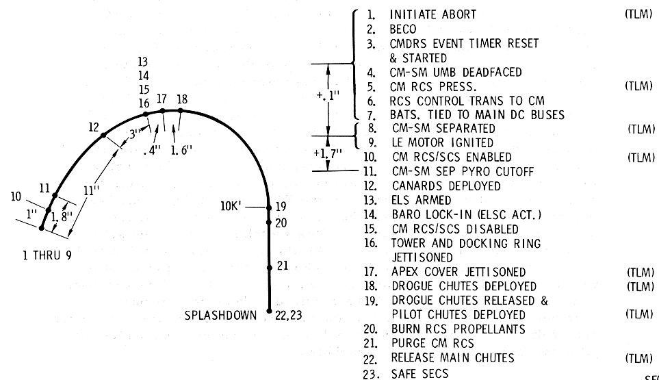
Mode 1B aborts may be categorized according to the
altitude at which the abort is initiated. The
Event Profile, Mode 1B Abort
T+42 Sec to 30,000 Feet illustrates the profile of an abort
initiated after abort mode switchover (paragraph 2. 9. 4. 14. 5) and
before reaching an altitude of approximately 30, 000 feet. Figure 2. 9-35
illustrates the profile of an abort initiated between the approximate
altitudes of 30, 000 and 100, 000 feet. Part of the ELSC functions (items
12 through 17 of the Event Profile, Mode 1B Abort T+42
Sec to 30,000 Feet) are automated by time-delay relay logic (ELSC
Operation) during mode 1B aborts initiated at the lower
altitudes.
Event Profile, Mode
1B Abort T+42 Sec to 30,000 Feet
All of the ELSC function s are automated by normal baro
switch operation (items 13 through 18, of the
Event Profile, Mode 1B Abort
˜̴
30,000 Feet to 100,000 Feet Diagram) during mode 1B aborts
initiated at the higher altitudes. Manually initiated requirements during
descent and postlanding functions of mode 1B aborts are the same as during
a nominal descent (paragraphs 2. 9
. 4. 13. 15 and 2. 9. 4 . 13.1 6).
Event Profile, Mode
1B Abort
˜̴ 3 0,000
Feet to 100,000 Feet Diagram
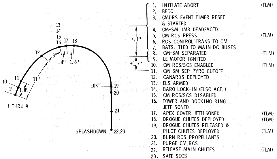
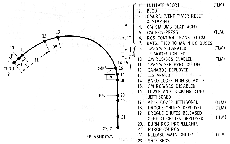
Mode 1C aborts (Event Profile, Mode 1C Abort
Diagram) are initiated at a time when the velocity of the LV
is higher than the trim point of the canards. This is between an
approximate altitude of 100,000 feet and normal LET jettison. The crew has
the prerogative of jettisoning the LET shortly after the abort is
initiated and utilizing the CM RCS for orientation similar to nominal
entry maneuvers; or all owing the canards to orient the LEV when the free
fall velocity is reduced, to the trim point. If the latter option is
elected there is a slight probability of an apex forward capture and
violent rotational rates when the canards become effective
aerodynamically. This slight probability can be avoided by imparting
energy to the falling LEV. The CM RCS may be utilized to maintain a +pitch
rate and this should be in excess of 5°/sec. There is no upper limit of
rates since the CM RCS is limited under these flight conditions.
Automation of ELSC functions during parachute descent and postlanding
functions are the same as a nominal descent.
Event Profile, Mode
1C Abort Diagram
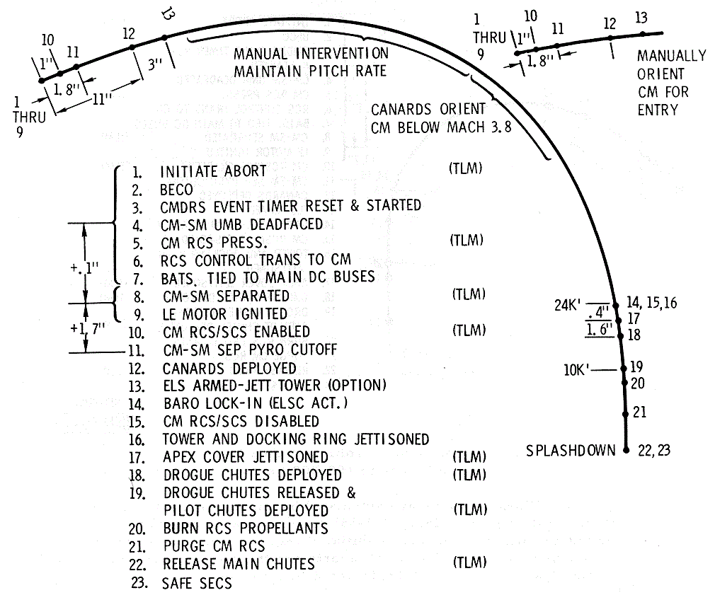
Sequential systems functions during an SPS abort are
designed to separate the CSM from the LV with automation conducive to
utilization of the SPS as required. Firing the SPS is not a function of
the sequential systems. The way this propulsion system is utilized, or if
it is utilized, is contingent on time into the mission, and maneuvering
requirements for a safe recovery. Sequential systems automation is the
same in all SPS aborts,
Event Profile, SPS Abort Diagram. This type abort may
be initiated any time after the LET is jettisoned until the CSM is
separated from the LV. All SPS aborts must be initiated manually because
the EDS automatic abort capability is lost when the LET is jettisoned (Launch
Escape Tower Jettison). Moreover, jettisoning of the LET
results in configuration change in the abort start circuits (Abort Start. (Zones 27 and 28-C
and -D)). ULLAGE relays in the MESC, zone 11-B, are energized
when the abort is initiated and the +X translation engines of the SM RC-S
are fired. The same signal that fires the engines also inhibits pitch and
yaw rate stabilization in the SCS. CSM-LV SEPARATE relays, zone 9-B, are
energized after a time delay of 3.0 seconds and the SC will be separated
from the LV (paragraph Separation of the Spacecraft From
the Launch Vehicle). RCS ENABLE ARM relays, zone 8-A, are
energized after a time delay of 0. 8 second and automated control of the
SM RCS will be enabled (Enable
Automated Control of the SM RCS). If the SC is equipped with a
docking probe it will be necessary to separate the LM docking ring (LM Docking Ring Separation)
at some time conducive to the situation. CM/SM separation and descent
operations are the same as during a nominal entry (Nominal Pre-entry and Descent).
Event Profile, SPS
Abort Diagram
The need is apparent in the sequential systems for one-
shot, high-energy, quick-response systems for rocket motor ignition,
physical separations, and deployment of earth recovery devices. To support
these needs, an electrical hot-wire initiator was selected as the standard
activation medium for the high-order ordnance systems required to satisfy
vehicle requirements. Range safety requirements dictate that electrically
activated ordnance components be capable of withstanding one watt and one
ampere for 5 minutes at the electrical-explosive interface without firing
or without degradation of initiator performance.
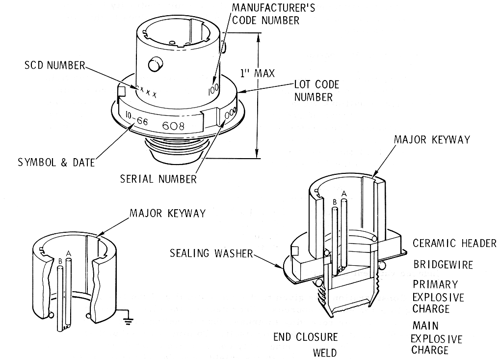
The hot bridge-wire initiator, hereinafter referred to
as the single bridgewire Apollo standard initiator (SBASI), is illustrated
in the Single
Bridgewire Apollo Standard Initiator Diagram. This device has
a primary ignition charge that is ignited by electrically heating a
one-ohm bridgewire. The primary charge ignites the main charge of the
initiator, which, in turn, generates high temperature gasses sufficient to
initiate the main charge of specialized explosive device. The SBASI is
designed to comply with the range safety requirements recapitulated in
paragraph PERFORMANCE
AND DESIGN DATA. A current of 3 .5 amperes on the bridgewire
will cause the SBASI to ignite in 10 milliseconds or less when subjected
to a temperature range of -65 to 300 °F. A current of 5.0 amperes on the
bridgewire will cause the SBASI to ignite in 15 milliseconds or less from
-260 to -65°F.
Single
Bridgewire Apollo Standard Initiator Diagram
Compliance With Design Requirements
The basic electrical design criteria for initiators are
rigidly specified in the Air Force Eastern Test Range Manual, Range Safety
Ma11ual, AFE TRM127-l (1 November 1966). In addition to the design
criteria specified in this manual, the following Apollo requirements have
been satisfied: ·
a.
The electroexplosive devices are
electrically shorted until they are fired to prevent inadvertent ignition
(Circuit
Concept Schematic, OPERATIONAL DESCRIPTION).
b.
At least two individually
operated switching circuits are incorporated between the initiator s and
their pyrotechnic battery terminals. These are "arming" switches and
"firing" switches which are illustrated in the
Sequential Systems Operational/Functional Diagram.
c.
Logic control circuits of
ordnance firing circuits receive operating from a source other than
pyrotechnic batteries.
d.
All logic and pyrotechnic firing
circuits are at least dual redundant.
e.
All logic timing circuits will
fail in the T = ∞
mode.
Component Selection and Installation
A portion of the high reliability achievement of the
sequential system is because basic rules in component design, assembly and
testing are closely followed. Carefully prepared specifications for
components include the expected maxima of shock, vibration, acceleration,
temperatures, margins, etc., not only at the time and interval of use, but
throughout the whole flight. Relay contact environment has been controlled
by hermetically sealed cases and potting. Components are screened 100
percent; that is, each relay is individually tested through repeated
cycling prior to acceptance. In the implementation of the series contact
circuits, the physical relays are mounted orthogonal to each other to
ensure the abnormal vibration or acceleration forces, which may be of
sufficient magnitude to prematurely close a given set of contacts, will
not be reflected into the same actuation plane of the other relay of the
same firing circuit. Verification of circuit integrity is important to
ensure that all circuit elements have been properly assembled and
installed.
Resistance measurements can validate that circuit
continuity is within acceptable limits in order that the required current
values to the SBASI can be guaranteed.
Fusistors are located in series with the output
contacts of the firing relays (Circuit
Concept Schematic). Thus individual protection of each
pyrotechnic firing circuit will prevent a current leakage path on any
given firing line. A continual discharge of pyrotechnic battery power is
impossible in this circuit design. These fusistors are specially designed
to withstand high acceleration and vibration levels. The resistance value
of these devices is 0.95 to 1.10 ohms at 25°C. The time-current operating
characteristics are reflected in the following tabulation:
|
Amperes |
Seconds |
|
20.0 |
0.03 to 0.17 |
|
10.0 |
0.20 to 1.20 |
|
8.0 |
0.30 to 8.00 |
|
7.0 |
0.40 to 20.00 |
Consideration was given to the susceptibility of the
firing circuit wiring to other energy sources. Unprotected, the circuits
leading to the SBASI could act as receiving antennas, thus funneling more
energy to the SBASI than it could pick up by itself. To minimize RF
pickup, the electrical leads from the firing relay contacts are twisted
(20 twists per 12 inches) and are shielded with the shield grounded at the
firing relay interface and at the case of the SBASI. Full 360-degree
shielding is provided between the shield and the SBASI case.
The Range Safety Manual requires that a positive
mechanical lock be used in the ARM/SAFE actuation device to prevent
movement from the safe to the armed position. A device developed for this
purpose is illustrated in the
Pyro Arm Switch Guard Diagram. Removal of the lock .is
accomplished by the insertion of a key that is provided to the astronaut
during the final prelaunch preparations.
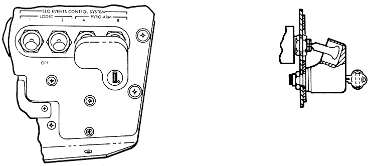
The TJM (Tower
Jettison Motor Diagram) is intended to provide thrust
capability, under normal mission operation, to effect adequate separation
of the LES from the CM, while the latter is undergoing acceleration by the
second stage booster; and, under abort conditions, to achieve adequate
separation of the LES from the CM after LEM burn out. The propellant
charge of the T JM consists of a case-bonded, star grain employing a
polysulfide ammonium perchlorate formulation.
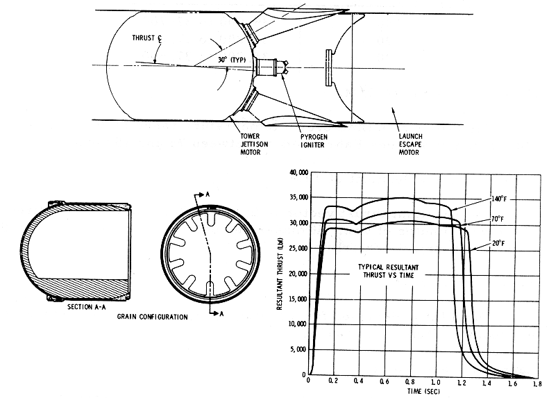
The average resultant thrust over the burning time when
measured at sea level is reflected in the following tabulation:
|
Motor Temperature (Degrees
Fahrenheit) |
Thrust Range (Pounds Force) |
|
140 |
31,200 to 36,000 |
|
70 |
29,400 to 33,900 |
|
20 |
28,000 to 32,400 |
|
Motor Temperature (Degrees
Fahrenheit) |
Thrust Impulse Range (Pounds -
Seconds) |
|
140 |
35,900 to 37,700 |
|
70 |
35,800 to 37,600 |
|
20 |
35,700 to 37,500 |
The thrust rise time over a temperature range of 20
minimum to 140 maximum degrees Fahrenheit is between 75 and 150
milliseconds.
Thrust Vector Alignment of TJM
The resultant thrust vector is in the pitch plan e in
the +z direction within ±30 minutes of yaw. It makes an angle of 3 to 4.5
degrees to the motor geometrical centerline.
The TJM is designed for a storage life of 5 years in a
temperature environment from 25 to 105 °F.
The LEM (Launch
Escape Motor Diagram) in conjunction with the PCM, is intended
to provide capability for the safe removal of the crew, inside the CM,
from a malfunctioning LV at any time from access arm retraction until
successful completion of second-stage ignition. The propellant of the LEM
consists of a case-bonded, eight-point star grain employing a polysulfide
ammonium perchlorate formulation.
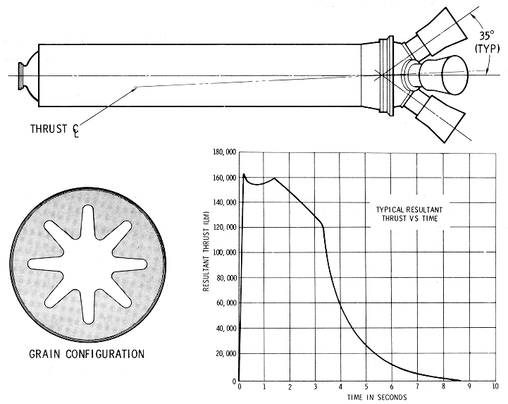
Resultant thrust of the LEM will fall within the
following limits when corrected to a temperature of 70°F and sea-level
barometric pressure:
a.
Thrust will not be greater than
177,000 pounds force (lbf). (This is equal to 200,000 lbf at 120 ° F in a
vacuum.)
b.
Thrust between 0. 2 and 2. 0
seconds after firing, current application will not be less than 135,000
lbf. (This is equivalent to 121,000 lbf at 20°F and sea-level barometric
pressure.)
The minimum delivered total impulse of tl1e LEM is
515,000 pound-seconds. The minimum delivered total impulse between 0.12
and 2.00 seconds is 233,064 pound-seconds.
The thrust rise time from the time of firing current
application to the time that the thrust reaches 90 percent of ignition
thrust is between 50 and 120 milliseconds. These limits apply regardless
whether one or two igniter cartridges are used.
Thrust Vector Alignment of LEM
The centerline of each nozzle forms an angle of 35
degree s ±15 minutes with the mean geometric motor centerline. The nozzles
located in the pitch plane have off-sized throats to give a resultant
thrust vector oriented 2 degrees 45 minutes to the mean geometric motor
centerline 1n the -Z direction. The maximum angular deviation of thrust
from the nominal thrust centerline during the first 0.20 second of burning
is ±15 minutes. During this same time period, the average roll moment
induced by nozzle alignment, internal ballistics, or any other cause will
not exceed 200 pound-feet.
The LEM is designed for a storage life of 5 years 1n a
temperature environment from 25 to 105 ° F.
The PCM (Pitch
Control Motor Diagram) in conjunction with the LEM, is
employed to place the LEV in the correct flight attitude for a successful
escape during mode 1A aborts. The propellant of the PCM consists of a
case-bonded, 14-point star grain employing a polysulfide ammonium
perchlorate formulation.
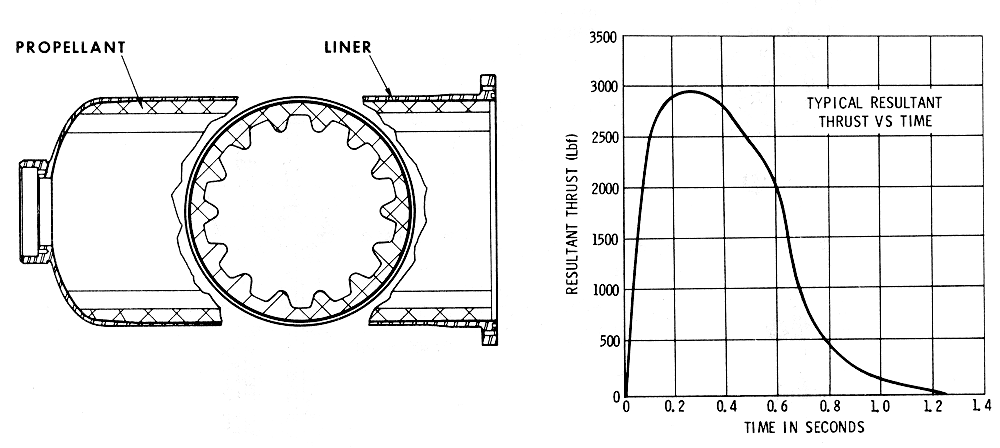
Resultant thrust of the PCM will not exceed 355.0 lbf
at 70°F and sea-level barometric pressure. This is equivalent to 4000 lbf
at 140°F in a vacuum.
The total delivered impulse of the PCM will be 1750
pound- seconds ±3 percent at 70°F and sea-level barometric pressure.
The thrust rise time from time of firing current
application to the time at which the thrust reaches 80 percent of maximum
will be between 60 and 120 milliseconds at 70°F.
Thrust Vector Alignment of PCM
The PCM is designed so that the resultant thrust vector
coincides with the centerline of the motor chamber mounting surfaces
within ±30 minutes.
The PCM is designed for a storage life of 5 years in a
temperature environment from 25 to 105 °F.
Two initiators are installed in each LES igniter (LES
Igniters Diagram). Boron pellets are ignited and they
in turn ignite the main charge of Pyrogen which spews flame into the grain
of the rocket motor.
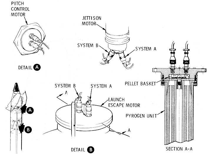
Hot gas pressure generated by the SBASI actuates the
squib valve (Squib
Valve Diagram). The spool shears the ends of inlet
and outlet plumbing which is sealed initially. Sixteen valves of this
configuration are incorporated in the fluid systems of the CM RCS (RCS
section).
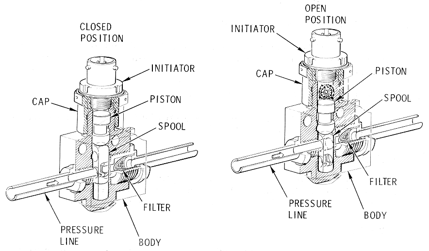
One of the specialized explosive devices used in some
of the Apollo ordnance systems is the detonator cartridge (Detonator Cartridge Assembly
Diagram). The SBASI is used in this application to ignite
additional explosive charges which are usually composed of lead azide and
RDX.
Detonator Cartridge
Assembly Diagram
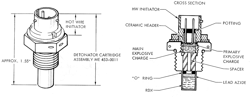
In one application, the high-energy concussion of
detonators is used to break frangible nuts (Tower Separation System Diagram).
Two detonators are installed in each nut and connected to firing circuits
A and B. Normally both detonators of each nut will fi r e and the nut will
be broken into two parts; however, if one detonator should fail, the nut
will be spread enough for thread clearance.
SLA Separation Ordnance System
Confined detonating fuse is used to transmit detonation
from detonators to detonating cord which is installed along cutting planes
of the SLA (Adapter
Separation System Diagram). Two detonators are utilized in
this explosive train for redundancy. One detonator is initiated by system
A firing circuits and the other by system B. Either of the detonators will
activate the entire ordnance system. Umbilical separation disconnect plug
assemblies are blown apart disconnecting the electrical wiring between the
LV and CSM. An umbilical disconnect swing arm is activated, which is the
interface between the LM and the GSE flyaway umbilical on one of the SLA
panels. Eight panel thrusters are also activated to start deployment of
the SLA panels.
Frangible links retain the clamps which are used to
secure the LM legs to the SLA. Detonators are used to break the links and
spring-loading opens the clamps (LM
Separation System Diagram). Either of the detonators will
break the frangible link. A pair of detonators is also utilized to
activate guillotine blades of the lower umbilical; these detonators are
not sympathetic and either guillotine blade will cut the wire bundle.
Deadfacing in this instance is accomplished by relay logic (Separation of LM From S-IVB).
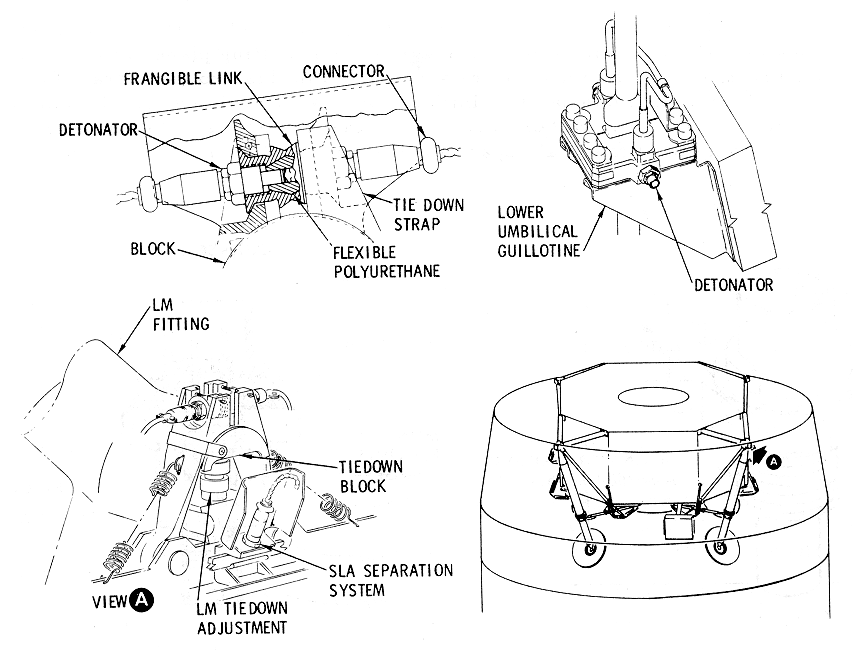
Redundant linear-shaped charges are used to cut three
tension tie straps which constitute the physical bond of the CM and SM (CM-SM
Separation System Diagram). A detonator is used to
explode each linear-shaped charge which is sympathetic to the other.
Either of the linear- shaped charges will cut the tension tie strap it is
mounted on; therefore, the sympathetic nature is not required to meet
minimum reliability requirements. The electrical-explosive interface
wiring to each detonator is also cut by the linear-shaped charges.
Solid propellant pressure cartridges (Pressure Cartridge Assembly
Diagram) have several applications in Apollo ordnance systems.
The SBASI is used to initiate a propellant charge. The size of the main
charge required is contingent on pressure requirements.
Pressure Cartridge
Assembly Diagram
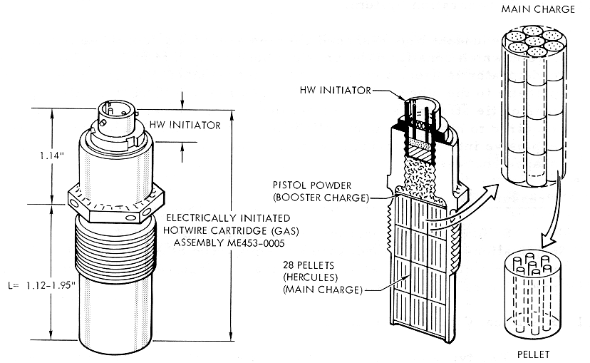
Electrical Circuit Interrupters
Two types of circuit interrupters are actuated when the
CM and SM are deadfaced during the separation sequence. Two CM-SM circuit
interrupters (CM-SM
Electrical Circuit Interrupter Diagram) are mechanized by
cams. Gas pressure forces a piston to move into a locked position and the
piston is connected to cam forks. Inclined planes on the cam forks forces
lift plates up which separate the mating parts of electrical receptacles.
Two SM circuit interrupters will deadface battery power, together with
ground returns, to the SM main buses (CM-SM Umbilical Assembly Diagram).
Gas pressure forces pistons against stops and the pins of the electrical
receptacles are pulled from the mating part. The piston assemblies include
the contact pins.
Two gas pressure cartridges are used to actuate canard
deployment (Canard
Actuator Diagram). Hot gas on one side of a piston
will cause the actuator shaft to retract. A closed hydraulic system on the
opposite side of the piston dampens transient loads, and check valves in
the fluid systems will maintain the piston in its actuated position. The
actuator shaft also incorporates a mechanical lock in the actuated
position.
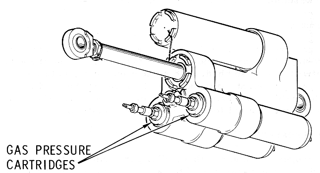
Two drogue parachutes, three pilot parachutes of the
main parachutes, and one drag parachute of the apex cover augmentation
system are deployed by mortar assemblies (Parachute Mortar Assemblies
Diagram). Two sympathetically initiated pressure cartridges
are mounted on the breech assembly of each mortar. A sabot, which is
effectively a fiberglass piston, is incorporated to protect the parachute
fabric from hot gas. The covers of the mortars are riveted and, when the
gas pressure causes the rivets to shear, the parachutes are ejected with
considerable force.
Parachute Mortar
Assemblies Diagram
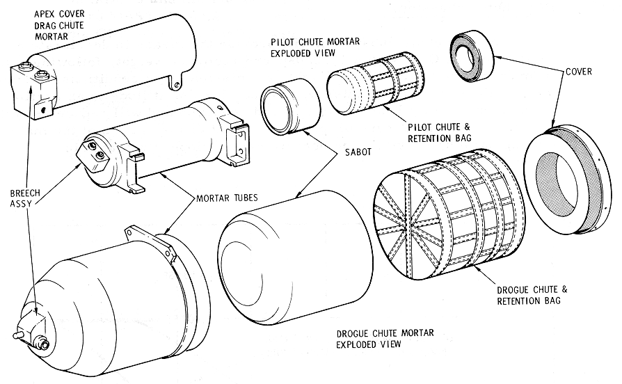
Five chisels are used to cut the risers of the drogue
and main parachutes (Parachute
Disconnect (Flower Pot) Diagram). Gas-pressure
cartridges are used to drive the chisels through the risers immediately
above the point where they are swaged. Two initiators are used on each gas
pressure cartridge.
Reefing line cutters (Reefing Line Cutter Diagram)
are designed to sever any coreless nylon cord with a breaking strength of
2000 pounds or less. The unit is mechanically initiated and provides a
time elapse between initiation and the severing of the cord. The primer,
time-delay train, and output charge are hermetically sealed. A storage
life of 3 years in a temperature environment from 20° to 140°F is designed
into the cutter. These cutters will not ignite or fire when subjected to a
temperature of 275°F for one hour; however, a cutter is not required to
perform after having been exposed to this temperature.
The para chute subsystem will provide the means to
decelerate and safely land the CM, with a 13, 000-pound recovery weight,
following entry from terrestrial orbit, lunar flight, or: mission abort
conditions. Deployment of the drogue parachutes will reduce the CM
attitude to an oscillatory, or stable, aft heat shield forward condition
and will reduce velocity to a point that will assure proper deployment and
operation of the main landing parachutes within the operational envelope
illustrated in the
Parachute Design Envelope.
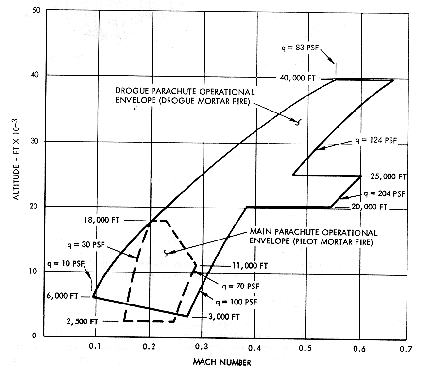
OPERATIONAL LIMITATIONS AND RESTRICTIONS
Since the sequential systems include numerous controls
for manual backup and/or intervention of automated functions, and since
several of the functions are time-critical, certain precautions should be
observed. Moreover, considerable versatility has been designed into the
systems, such as alternate electrical power selection. Serious damage
could result if correct procedures are not followed.
Alternate Selection of Logic Power
It would be possible to couple a defective battery to a
good one, and serious damage to the electrical power supply could result
if the circuit breakers, described in the Logic
Power
paragraph, are not utilized properly. The BAT C TO BAT BUS A
and B circuit breakers (CB15andCB24), zone42-B are included in the system
to enable the utilization of ENTRY AND POST LANDING BATTERY C in the event
of a power failure in either of the ENTRY AND POST LANDING BATTERIES A or
B. If the contingency of alternate power utilization should occur, the
defective battery should be isolated before the appropriate BAT C TO BAT
BUS A or B circuit breaker is closed. Additional information on this
subject is included in the Electrical Power section.
Alternate Selection of Pyro Power
If the circuit breakers described in the Pyro Power paragraph, are not
utilized properly, serious damage to the electrical supply could result.
The potential hazard is the same as described in the
Alternate Selection of Logic
Power paragraph,
except in this instance the electrical power of the PYRO Systems, zones 41
through 43-D and -E, is concerned. The BAT BUS A and B TO PYRO BUS TIE
circuit breakers (CB 18 and CB 19) are included in the system to be used
in the event of a failure of PYRO BATTERY A or B. If such a power failure
should occur, the appropriate SEQ A or B circuit breaker (CB16 or CB17)
should be opened before coupling the appropriate ENTRY AND POST LANDING
battery to the PYRO power system.
Control for Arming Pyro Systems
Battery power is required to arm or safe PYRO buses (EDS
Bus Changeover. (Zones 36, 37-A, and-B)). It is therefore
necessary to close the SECS ARM BAT A circuit breakers (CBI), and/or its
counterpart in system B, zone 39-C, before the motor switch (K1) in the
LDEC, zones 39 and 40-E and -F, can be operated to energize or de-energize
the PYRO buses. This feature is designed into the system for power
conservation during a mission when the docking probe is being used. The
procedures for the utilization of battery power for control of PYRO power
will consequently differ somewhat during the various phases of a mission.
Status of Logic and Pyro Buses
It will be necessary for the flight crew to verify the
status of LOGIC and PYRO buses, i.e., armed or safe, through the MSFN.
Displays for this status are not included in the CM.
Utilization of Controls for CSM/LV Separation
When the CSM/LV SEP switch is used (Separation of the Spacecraft From
the Launch Vehicle
), it should be held closed for approximately one second (0.
8 second minimum) for the time-delay-relay logic to perform as it was
designed.
Utilization of Controls for CM/SM Separation
When the CM/SM SEP switches are used, they must be held
closed for 0. 1 of a second for the time-delay- relay logic to perform as
it was designed (CM/SM
Separation Control).
Manual Control of ELSC Functions
Under certain entry conditions, erratic aerodynamic
damping coefficients, wind gusts, and shears, the CM may become un stable.
If this should occur, the apex cover and drogue parachutes may be manually
deployed early. This will stabilize and keep the CM in the proper
descending attitude. See the Parachute
Design Envelope for the drogue deployment design envelope. The
following precautions should be observed:
a.
Manual initiation of drogue
parachute deployment should never be accomplished above 40, 000 feet
during entry.
b.
The CM RCS must be turned off
prior to apex cover jettison.
c.
Manual initiation of apex cover
jettison must not be executed with the L ET attached.
d.
Manual initiation of drogue
parachute deployment must not be executed with the apex cover on the
vehicle.
e.
Manual initiation of main
parachute deployment must not be executed prior to drogue deployment.
f.
Manual initiation of main
parachute deployment must be accomplished above 2500 feet.
g.
Two circuit breakers are
incorporated in MESC PRYO circuits to the main parachute release ordnance
devices. These circuit breakers should not be closed until after the CM
has landed (paragraph 2.9.3.4 .2.3).
h.
It is impossible to release the
main parachutes with the ELS switch in the MAN position. This switch must
be in the AUTO position and the 14-second time delays in the ELSC (TD 3
and TD 4), zone 6-C, expired before the MAIN RELEASE switch is armed.
}~
I