APOLLO
11 OPERATIONS HANDBOOK BLOCK II SPACECRAFT
VOLUME
l SPACECRAFT DESCRIPTION
'
STABILIZATION
AND CONTROL SYSTEM (SCS) (SC 106 AND SUBS UNLESS OTHERWISE NOTED)
CONTROLS,
SENSORS, AND DISPLAYS
Rotation
Control Interfaces Schematic
Attitude
Set Control Panel Diagram
Gimbal
Position and Fuel Pressure Indicator
Gimbal
Position and Fuel Pressure Indicator Diagram
Flight
Director Attitude Indicator
Flight
Director Attitude Indicator Diagram
Spacecraft
Control Switching Interfaces
SGS
Attitude Reference Overview
FDAI
Attitude Select Logic Schematic
FDAI
Rate Select Logic Schematic
Total
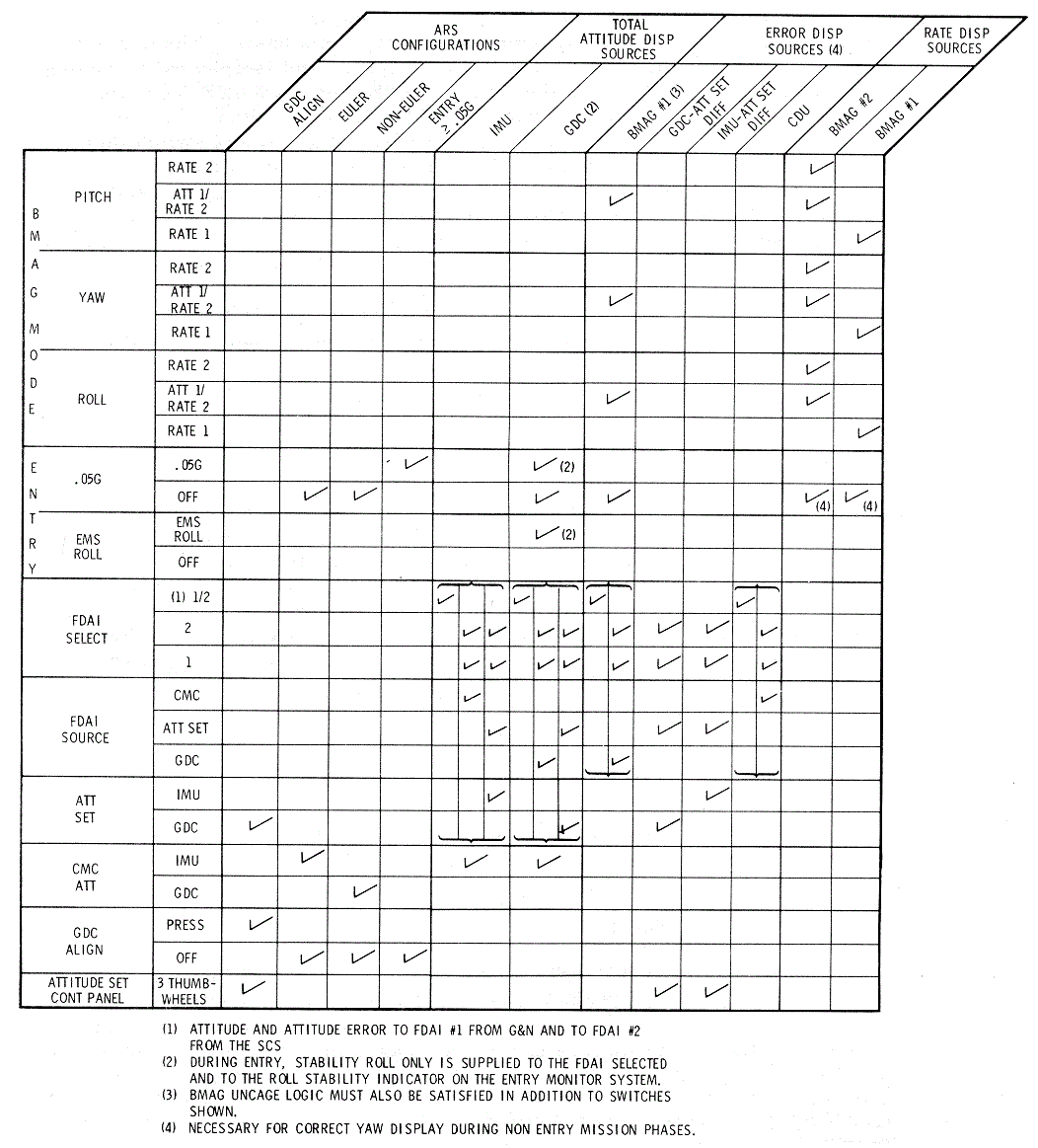
Attitude and Error Display Sources
BMAG
Logic and Outputs Schematic
Translation
Control Interfaces Schematics
Auto
RCS Enabling Power Schematic
Reaction
Control Subsystem Interface
Auto
RCS Signal Flow Schematic
CM
PROPELLANT JETT-DUMP Control
SCS
Attitude and Thrust Vector Control System Schematic
Attitude
Deadband Switch Position Table
SCS
D-C Power Distribution Schematic
ACS
Control Capabilities Diagram
Engine
Ignition, Thrust On- Off Logic
Engine
Ignition-Thrust On-Off Logic Schematic
SCS
D-C Power Distribution Schematics
Corridor
Verification Indicators
EMS
Corridor Evaluation Diagram
Delta
V /Range-To-Go Indicator
EMS
ln-Flight Instructions for delta V, VHF Ranging, Self-Test and Entry
Diagram
EMS
Lunar Non-Exit Range Limit Pattern
EMS
Lunar 3500 NM Range Limit Pattern
Threshold
and Corridor Verification Circuits
Scroll
Assembly G Axis Drive Circuits
Scroll
Assembly Velocity Axis Drive Circuits
Delta
V/RANGE Display Circuits
Roll
Stability Indicator Drive
STABILIZATION AND
CONTROL SYSTEM
(SCS) (SC 106 AND
SUBS UNLESS OTHERWISE NOTED)
The stabilization and control subsystem (SCS) provides
a capability for controlling rotation, translation, SPS thrust vector, and
displays necessary for man in the loop control functions.
The SGS is divided into three basic subsystems:
attitude reference, attitude control, and thrust vector control. These
subsystems contain the elements which provide selectable functions for
display, automatic and manual attitude control, and thrust vector control.
All control functions are a backup to the primary guidance navigation and
control subsystem (PGNCS). The SGS provides two assemblies for interface
with the propulsion subsystem; these are common to SCS and PGNCS for all
control functions. The main display and controls panel contains the
switches used 1n selecting the desired display and control configurations.
The SGS interfaces with the following spacecraft
subsystems:
Telecommunications Subsystem-Receives all down-link
telemetering from SCS.
• Electrical Power
Subsystem-Provides primary power for SCS operation.
• Environmental Control
Subsystem-Transfers heat from SCS electronics.
• Sequential Events Control
Subsystem-Provides abort switching and separation enabling of SCS reaction
control drivers and receives manual abort switch closure from the SCS.
• Orbital Rate Drive
Electronics for Apollo and LM-Interfaces with the pitch axis of the FDAI
ball to give a local vertical referenced display.
• Guidance Navigation and
Control Subsystem:
·
Provides roll, pitch, and yaw
total attitude and attitude error inputs for display.
·
Provides RCS on-off commands to
the SCS interface assembly for attitude control.
·
Provides TVC servo commands to
the SCS interface assembly for automatic thrust vector· control
·
Provides automatic SPS on-off
command to SCS interface assembly for Delta V control
·
Receives switch closure signals
from the SCS translation and rotation controls.
·
Entry monitor subsystem: the EMS
provides SPS enabling/disabling discretes to the SCS thrust on-off logic
for tl1e SPS.
• Propulsion subsystem:
o
The service propulsion subsystem
receives thrust vector direction commands and thrust on- off commands from
the SCS that can originate in the PGNCS or the SCS.
o
The reaction control subsystem
receives thrust on-off commands from the SCS that can originate in the
PGNCS or the SCS.
Detailed descriptions of the SCS hardware, attitude
reference subsystem, attitude control subsystem, and thrust vector control
subsystem are contained in the following paragraphs.
CONTROLS, SENSORS, AND DISPLAYS
As an introduction to the stabilization and control
system (SCS) a brief description is given of the hardware comprising one
complete system. A more detailed discussion follows for the hand controls,
displays, and gyro assemblies. The configurations within the SCS resulting
from panel 1 switch positions are also presented.
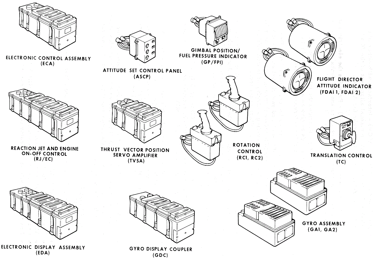
The function of the SCS hardware shown in the SCS Flight Hardware Diagram as
follows:
Electronic Control Assembly (ECA) - Contains the
circuit elements required for summing, shaping, and switching of the r ate
and attitude error signals and manual input signals necessary for
stabilization and control of the thrust vector and the spacecraft
attitude.
·
Reaction Jet and Engine ON-OFF
Control (RJ/EC) - Contains the solenoid drivers and logic circuits
necessary to control both the RCS automatic solenoid coils and SPS
solenoid control-valves.
·
Electronic Display Assembly (EDA)
- Provide s the interface between the signal sources to be displayed and
the FDAIs and GPI. The EDA also provides signal conditioning for telemetry
of di splay signals.
·
Attitude Set Control Panel (ASCP)
- Interfaces with either of the total attitude sources to enable manual
alignment of the SGS total attitude. Provides an attitude error for
display.
·
Thrust Vector Servoamplifier
(TVSA) - Provides the electrical interface between the command electronics
and the gimbal actuator for positioning the SPS engine.
·
Gyro Display Coupler (GDC) -
Provides the interface between the body rate sensors and displays to give
an accurate readout of spacecraft attitude relative to a given reference
coordinate system.
·
Gimbal Position and Fuel Pressure
Indicator (GP/ FPI) - Provides a redundant display of the SPS pitch and
yaw gimbal angles and a means of manually trimming the SPS before
thrusting. The indicator has the alternate capability of providing a
display of launch vehicle (S-II and S-IVB) propellant tank ullage
pressures.
·
Rotation Controls (RC) (2) -
Provides a means of exercising manual control of spacecraft rotation in
either direction about each axis. Also the RC may be used for manual
thrust vector control. It provides the capability to control spacecraft
communications with a push- to - talk trigger switch.
·
F light Director Attitude
Indicator (FDA!) (2 Only) - Provides to the crew a display of spacecraft
attitude, attitude error, and angular rate information from the PGNCS or
SCS.
·
Translation Control (TC) -
Provides a means of exercising manual control over rectilinear motion of
the spacecraft in both directions along the three spacecraft axes. It also
provides the capability for manual abort initiation during launch by ccw
rotation. Transfer of SC control from PGNCS to SCS is accomplished by cw
rotation.
·
Gyro Assemblies (GA) (2) - Each
gyro assembly contains three bodymounted attitude gyros (BMAG) together
with the electronics necessary to provide output signals proportional to
either angular rate or to angular displacement.

The SGS controls and displays consist of the following
assemblies:
·
Rotation control (RC) - 2 units
·
Translation control (TC)
·
Attitude set control panel (ASCP)
·
Gimbal position and fuel pressure
indicator (GP/ FPI)
·
Flight director attitude
indicator (FDAI) - 2 assemblies
Two identical rotation controls (RCs) are provided. The
controls are connected in parallel so that they operate in a redundant
fashion without switching. Pitch commands are commanded about a
palm-centered axis, yaw commands about the grip longitudinal axis, while
roll commands result from a left-right motion (Rotation Control Diagram).
Within the RC there are three command sources per axis:
1.
Breakout Switches (±BO) - A
switch closure occurs whenever the RC is moved 1. 5 degrees from its null
position. Separate switches are provided in each axis and for each
direction of rotation. These six breakout switches are used to provide:
command signals to the command module computer (CMG), SGS minimum
impulses, acceleration commands, BMAG cage signals, and proportional rate
command enabling.
2.
Transducers - Transducers produce
a-c signals proportional to the rotation control displacement from the
null position. These signals are used to command spacecraft rotation rates
during SGS proportional rate control and to command SPS engine gimbal
position during manual thrust vector control (MTVC ). One, two, or all
three transducers can be used simultaneously, generating corresponding
command signals.
3.
Direct Switches - Redundant
direct switches will close whenever the control is moved a nominal 11
degrees from its null position (hardstops limit control movement to ±11. 5
degrees from null in all axes). Separate switches are provided in each
axis and for each direction of rotation. Direct switch closure will
produce acceleration commands through the RCS direct solenoids.
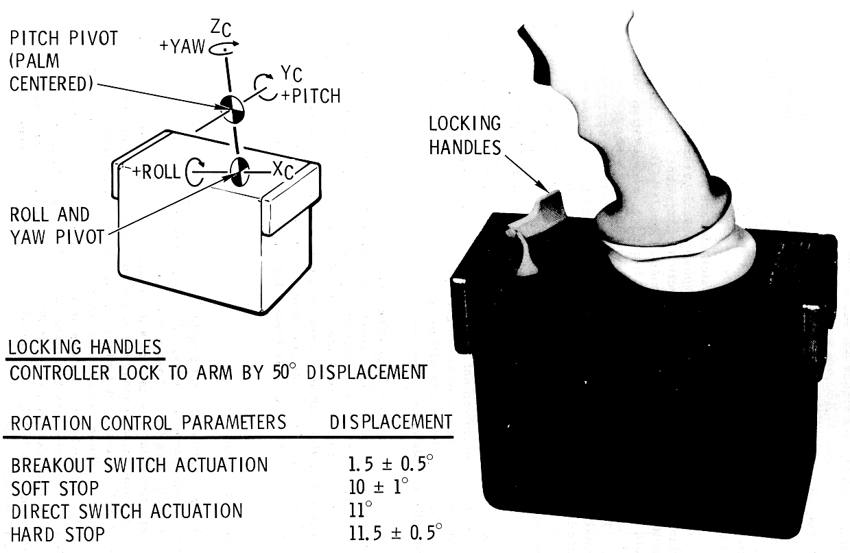
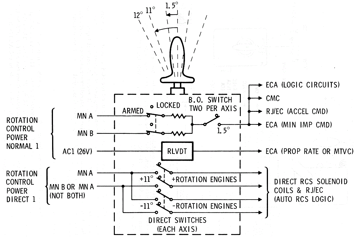
The rotation control is provided with a tapered female
dovetail on each end of the housing. This dovetail mates with mounting
brackets on the couch armrests. When attached to the armrests, the input
axes are approximately parallel
with spacecraft body axes. The
Rotation Control Interfaces
Schematic illustrates
control motions about its axis and the resulting commands to the RCS,
PGNCS, or SCS. A trigger-type push-to-talk switch is also located in the
control grip. Redundant locking devices are provided on each control.
Rotation Control
Interfaces Schematic
The translation control provides a means of
accelerating along one or more of the spacecraft axes. The control is
mounted with its axes approximately parallel to those of the spacecraft.
The spacecraft will accelerate along the X-axis with a push-pull motion,
along the Y-axis by a left-right motion, and along the Z-axis by an
up-down command (Translation
Control Diagram). Redundant switches close for each direction
of control displacement. These switches supply discrete commands to the
CMG and the RJ /EC. A mechanical lock is provided to inhibit these
commands. In addition the T -handle may be rotated about the longitudinal
axis:
a.
The redundant clockwise (CW)
switches will transfer spacecraft control from CMG to SCS. It may also
transfer control between certain submodes within the SGS.
b.
The redundant counterclockwise
(CCW) switches provide for a manual abort initiation during the launch
phase. A discrete signal from switch closure is fed to the master events
sequence controller (MESC) which initiates other abort functions.
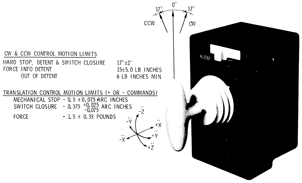
Neither the CW or CCW functions are inhibited by the
locking switch on the front of the controller. The T-handle will remain in
the CW or CCW detent position without being held, once it is rotated past
approximately plus or minus 12 degrees.
Attitude Set Control Panel (ASCP)
The ASCP (Attitude Set Control Panel
Diagram) provides, through thumbwheels, a means of positioning
differential resolvers for each of the three axes. The resolvers are
mechanically linked with indicators to provide a readout of the dialed
angles. The input signals to these attitude set resolvers are from either
the IMU or the GDC. The inertial (Euler) attitude error output signals are
sine functions of the difference angles between the desired attitude, set
by the thumbwheels, and' the input attitude from the GDC or IMU. The GDC
Euler output can be used to either align the GDC or to provide fly- to
indications on the FDAI attitude error needles.
Attitude Set
Control Panel Diagram
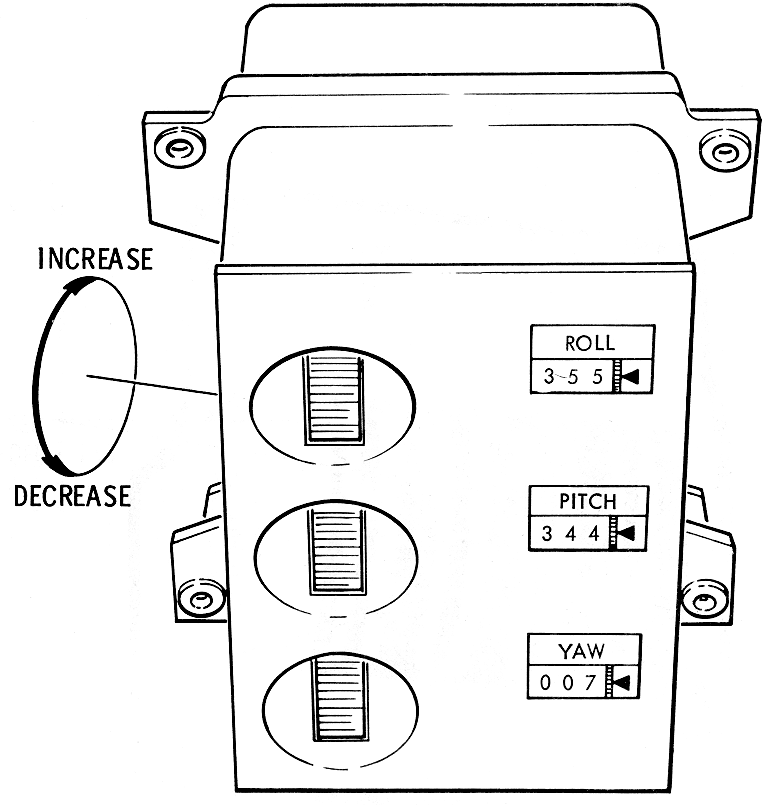
a.
Indicates resolver angle in
degrees from electrical zero, and allows continuous rotation from 000
through 359 to 000 without reversing the direction of rotation.
b.
Graduation marks every 0.2 degree
on the units digit.
c.
Pitch and roll are marked
continuously between O and 359. 8 degrees. Yaw is marked continuously from
Oto 90 degrees a nd from 270 to 359. 8 degrees.
d.
Readings increase for an upward
rotation of the thumbwheel s. One revolution of the thumbwheel produces a
20-degree change in the resolver angle and a corresponding 20-degree
change i n the counter reading.
The counter readouts are floodlighted and the
nomenclature (ROLL, PITCH, and YAW) is backlighted by electroluminescent
lighting.
Gimbal Position and Fuel Pressure Indicator (GP/ FPI)
The GP/FPI (Gimbal Position and Fuel Pressure
Indicator Diagram) contains redundant indicators for both the
pitch and yaw channels. During the boost phases, the indicators display
S-II and S-IVB propellant tank ullage pressures. S-II fuel pressure (or
S-IVB oxidizer pressure depending on the launch vehicle configuration) is
on the redundant pitch indicators while S-IVB fuel pressure is on the two
yaw indicators. The gimbal position indicator consists of two dual
servometric meter movements, mounted within a common hermetically sealed
case. Scale illumination uses electroluminescent lighting panels.
Gimbal Position and
Fuel Pressure Indicator Diagram
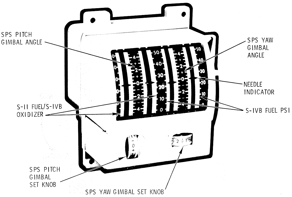
For an SCS del ta V mode, manual SPS engine gimbal trim
capability is provided. Desired gimbal trim angles are set in with the
pitch and yaw t rim thumbwheels. The indicator displays SPS engine
position relative to actuator null and not body axes. The range of the
engine pitch and yaw gimbal displays are ±4.5 degrees. This range is
graduated with m arks at each 0.5 degree and reference numeral at each 2
-degree division. The range of the fuel pressure scale is O to 50 psi with
graduations at each 5 - psi division, and reference numerals at each
10-psi division. A functional description of the GPI display circuitry
which shows the redundancy is in GPI
Signal Flow.
.
Flight Director Attitude Indicator (FDAI)
The FDAIs provide displays to the crew of angular
velocity (rate), attitude error, and total attitude (Flight Director Attitude
Indicator Diagram). The body rate (roll, yaw, or pitch)
displayed on either or both FDAIs is derived from the BMAGs in either gyro
assembly 1 or 2. Positive angular rates are indicated by a downward
displacement of the pitch rate needle and by leftward displacement of the
yaw and roll rate needles. The angular rate displacements are "fly-to"
indications as related to rotation control direction of 1notion required
to reduce the indicated rates to zero. The angular rate scales are marked
with graduations at null and ±full range, and at ±1/5, ±2/5, ±3/5, and
±4/5 of full range. Full-scale deflection ranges are obtained with the
FDAI SCALE switch and are:
•
Pitch r ate: ±1 deg per sec, ±5
deg per sec, ±10 deg per sec
•
Yaw rate: ±1 deg per sec, ±5 deg
per sec, ±10 deg per sec
•
Roll r ate: ±1 deg per sec, ±5
deg per sec, ±50 deg per sec
Flight Director
Attitude Indicator Diagram
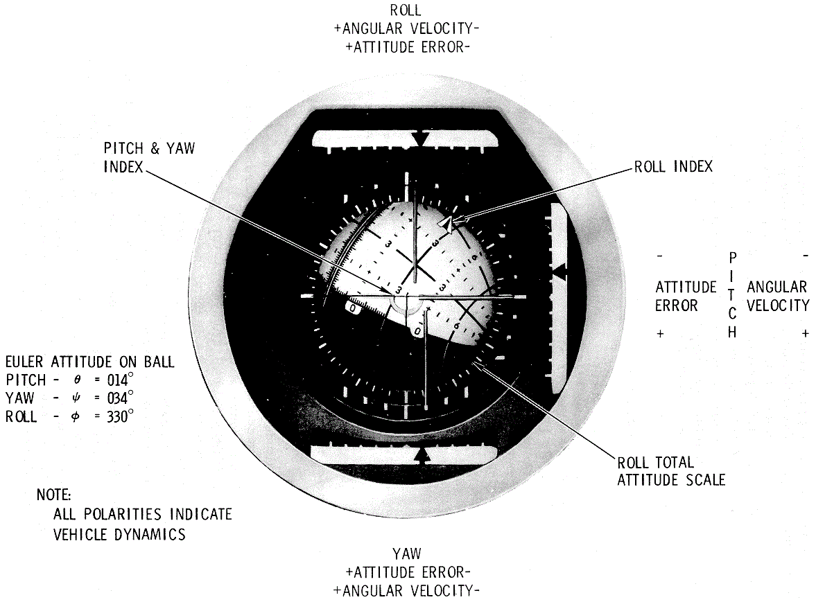
Servometric meter movements are used for the three rate
indicator needles. The FDAI attitude error needles indicate the
difference between the actual and desired spacecraft attitude. The
attitude error signal ca n be derived from several sources: The uncaged
BMAGs from GA-1, the CDU s (PGNCS), or the ASCP-GDC/IMU (ARS Switching Diagram).
Positive attitude error is indicated by a downward dis placement of the
pitch error needle, and by a leftward displacement of the yaw and roll
error needles. The attitude error needle displacements are "fly-to"
indications as related to rotation control direction of motion, required
to reduce the error to zero. The ranges of the error needles are ±5
degrees or ±50 degrees for full- scale roll error, and ±5 degrees or ±15
degrees for pitch and yaw error. The error scale factors are selected by
the FDAI SCALE switch that also establishes the rate scales. The pitch and
yaw attitude error scales contain graduation n1arks at null and ±full
scale, and at ±1 /3 and ±2/3 of full scale. The roll attitude scale
contains marks at null, ±1 / 2, and ±full scale. 1' he attitude error
indicators utilize servometric meter movements.
Spacecraft orientation, with respect to a selected
inertial reference frame, is also displayed on the FDAI ball. This display
contains three servo control loops that are used to rotate the ball about
three independent axes. These axes correspond to inertial pitch, yaw, and
roll. The control loops can accept inputs from either the IMU gimbal
resolvers or tl1e GDC resolvers. Selecting the source is covered in
Functional Switching Concept
.
The control loops are proportional. servos; therefore,
the angles of rotation of the ball must correspond to the resolver angles
of the source. The FDAI, illustrated in figure 2. 3- 6, has the following
markings:
a.
Pitch attitude i s represented on
the ball by great semicircles. The semicircle (as interpolated), displayed
under the FDAI inverted wing symbol, is the inertial pitch at the time of
readout. The two semicircles that make up a great circle correspond to
pitch attitude s of Q and G+ 180 degrees.
b.
Yaw attitude is represented by
minor circles. The display readout is similar to the pitch readout. Yaw
attitude circles are restricted to the intervals - 270 to 360 degrees (0°)
and O (360°) to 90 degrees.
c.
Roll attitude is the angle
between the wing symbol and the pitch attitude circle. The roll attitude
is more accurately displayed on a scale attached to the FDAI mounting,
under a pointer attached to the roll (ball) axis.
d.
The last digits of the circle
markings are omitted. Thus, for example, 3 corresponds to 30, and 33
corresponds to 330.
e.
The ball is symmetrically
marked (increment wise) about the 0-degree yaw and 0/ 180-degree pitch
circles. The following comments provide clarification for areas of the
ball not shown in Flight Director Attitude
Indicator Diagram.
i.
Marks at I -degree increments are
provided along the entire yaw 0-degree circle.
ii.
The pitch 180-degree semicircles
has the same marking increments as the 0-degree semicircle.
iii.
Numerals along the 300- and
60-degree yaw circles are spaced 60-pitch degrees apart. Note that
numerals along the 30-degree yaw circle are spaced 30-pitch degrees apart.
f.
f. The red areas of the ball,
indicating gimbal lock, are defined by 270 < yaw < 285 degrees and
75 < yaw < 90 degrees.
The Block II SCS utilizes functional switching concepts
as opposed to "mode select" switching mechanized in the Block I system.
Functional switching requires manual switching of
numerous independent panel switches in order to configure the SCS for
various mission functions (e.g., midcourse, delta Vs, entry, etc.). Mode
switching would, for example, employ one switch labeled "midcourse" to
automatically accomplish all the necessary system gain changes, etc., for
that mission phase. Thus mode selection simplifies the crew tasks
involved, but limits system flexibility between various mode
configurations.
Function select switching, on the other hand, requires
more crew tasks, but offers flexibility to select various gains, display
scale factors, etc., as independent system capabilities. Function select
switching also allows flexibility to "switch out" part of a failed signal
path without affecting the total signal source (e.g., SCS in control of
the vehicle with GN displays still presented to the crew).
The FDAI switches determine the source of display data,
the FDAI selected, and the full-scale deflections of the attitude error
and rate needles. The source of rate information for display will always
be from BMAG 2 unless BMAG 1 is put into a backup rate configuration.
Other switches also modify the data displayed and these will be pointed
out as they are discussed. Both FDAIs are also assumed to be properly
energized from the power switching panel.
Spacecraft Control Switching Interfaces
There are two sources of vehicle controls selectable
from the SC main display console: SCS or CMC. CMC is the primary method of
control and the SCS provides backup control. The vehicle attitude control
is obtained from the reaction control engines and the thrust vector
control from the service propulsion engine.
SGS Attitude
Reference Overview

Gyro Display Coupler (GDC)
The purpose of the GDC is to provide a backup attitude
reference system for accurately displaying the spacecraft position
relative to a given set of reference axes. Spacecraft attitude errors can
be displayed on an FDAI using the ASCP-GDC difference. This error signal
provides a means of aligning the attitude reference system to a fixed
reference while monitoring the alignment process on the error needles; or
it could be used in conjunction with manual maneuvering of the spacecraft
with the error needles representing fly-to-commands.
The GDC can be configured for the following
configurations:
GDC align - Provides a means of aligning the GDC to a
given reference.
•
Euler - Computes total i11ertial
attitude from body rate signal inputs.
•
Non-Euler - Converts analog body
rate signals to digital body rate pulses.
•
Entry (. 05 G) - Provides
redundant outputs of attitude changes with respect to the roll stability
axis.
Panel switch positions necessary to obtain each
particular GDC function are discussed below.
a.
The GDC align mode is used when
aligning the GDC Euler angles (shafts) to the desired inertial reference
selected by the ASCP thumb wheels (resolvers). This is done by interfacing
the GDC resolvers with the ASCP resolvers (per axis) to generate error
signals which are proportional to the sine of the difference between the
resolver angles. (See FDAI Attitude Select Logic
Schematic.) When the GDC ALIGN switch is pressed, these error
signals are fed back to the GDC input to drive the GDC /ASCP resolver
angular difference to zero. During the align operation all other inputs
and functions for the GDC are inhibited. When the EMS ROLL switch is up
and the GDC ALIGN switch is pressed, the RSI pointer rotates (open loop)
in response to yaw ASCP thu1nbwheel rotations.
b.
In the Euler configuration, the
GDC accepts pitch, yaw, and roll d-c body rate signals from either gyro
assembly and transforms them to Euler angles to be displayed on either
FDAI ball. The GDC Euler angles also interface with the attitude set
control panel (ASCP) to provide Euler angular errors, which are
transformed to body angular errors for display on either FDAI attitude
error indicators.
c.
c.
With the CMC A TT switch in the GDC position, pitch, yaw, and roll d - c
body rate signals from either gyro assembly are converted to digital body
rate signals and sent to the G&N command module computer. Power is not
only removed from both FDAI ball-drive circuits when this configuration is
selected, but ASCP-generated errors are also removed.
d.
In the entry mode (>/= . 05
G), the GDC accepts yaw and roll d-c rate signals from:
1. Either gyro assembly, and
computes roll attitude with respect to the stability axis to drive the RSI
on the entry monitor system.
2. Gyro assembly 1, and
computes roll attitude with respect to the stability axis to drive either
FDAI 1 or FDAI 2 in roll only.
FDAI Attitude
Select Logic Schematic
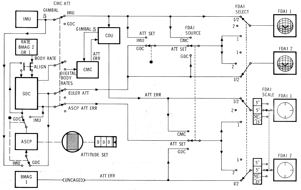
The two FDAI s display total attitude and attitude
errors that may originate within the SCS or PGNCS. They also display
angular rate from the SCS. The flight crew establishes the FDAI sources by
panel switch selection. (See FDAI Rate Select Logic Schematic and ARS Switching Diagram.)
FDAI Rate Select
Logic Schematic
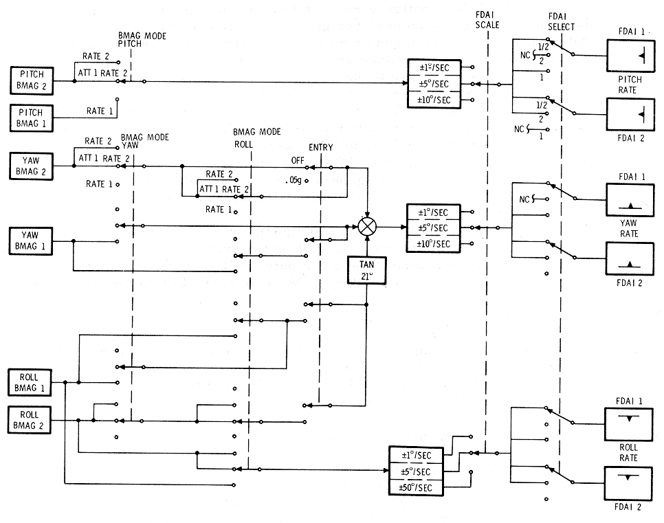
Total Attitude and Error Display Sources
The total attitude and attitude error display
selections result from combinations of panel switch positions (FDAI Attitude Select Logic
Schematic). When both FDAIs are selected, the platform gimbal
angles will always be displayed on FDAI 1 while GDC Euler angles will be
displayed on FDAI 2. In order to select the source of attitude display to
a particular FDAI, that FDAI and source (G&N or SCS) must be selected
(figure ARS
Switching Diagram). The other FDA I will be inactive. It
should be noted that any time total attitude is to be displayed on either
FDAI, the CMC ATT Switch must be in the IMU position.
The FDAI attitude display may be modified by a
NASA-supplied Orbital Rate Display-Earth and Lunar (ORDEAL) unit. The
ORDEAL unit is inserted electrically in the pitch channel between the
electronic display assembly and FDAI to provide a local-vertical display
in the pitch axis of either (or both) FDAIs. Control s on the unit permit
selection of earth or lunar orbits and orbital altitude adjustment.
The FDAI attitude error display source can be either
the SCS or the G&N, with two sources per system. The attitude error
sources are as follows:
a.
The BMAG 1 error display is an
indication of gimbal precession about its null point, assuming the gyro is
uncaged, and may only be displayed when the SOURCE switch is in the GDC
position or when the FDAI SELEG T switch is in the 1 / 2 position.
b.
Euler angles from the GDC
interface with the ASCP to provide an Euler angle error (GDC -attitude set
difference signal) which is then transformed to body angle errors for
display on either FDAI. This display source facilitates manual maneuvering
of the spacecraft to a new inertial attitude that was dialed in on the
attitude set thumbwheels.
c.
Inertial gimbal angles from the
IMU interface with the ASCP to generate inertial error (IMU-attitude set
difference signal) which may be displayed on either FDAI. Thus, if the
error needles were nulled using the thumbwheels on the ASCP, the ASCP
indicators would then indicate the same inertial reference as the
platform.
d.
The CMC generates attitude errors
that are a function of the program. These will be displayed when the
SOURCE switch is in the CMC position, or when the FDAI SELECT switch is in
the 1/2 position.
The rate display sources (FDAI Attitude Select Logic
Schematic and ARS
Switching Diagram) will always be from either of the two gyro
assemblies on a per-axis basis. The nor mal source for rate display will
be the BMAG 2 gyros, and is selected by having the BMAG MODE switches in
the A TT 1 /RATE 2 or the RATE 2 position. The backup source is selected
when the BMAG MODE switch is in the RATE 1 position. This will rate cage
the BMAG 1 gyros and switch their outputs to the FDAI rate needles. When
the ENTRY - . 05 G switch is placed up, the roll rate gyro output is
modified by the tangent 21 degrees and summed with the yaw rate. This
summation results in a cancellation of the yaw rate sensed due to the CM
rolling about the stability axis. Since this is a summation of a-c rate
signals and since the gyro assemblies are supplied from separate a-c
buses, selecting backup rate (BMAG 1) in yaw will automatically select the
backup rate gyro (BMAG 1) in roll and vice versa. This prevents any phase
difference from the two buses from affecting the summation of the two rate
signals.
ATTITUDE CONTROL SUBSYSTEM (ACS)
The SCS hardware used in controlling the spacecraft
attitude and translation maneuvers include the gyro assemblies, rotation
and translation controls, and two electronic assemblies. The electronic
control assembly (ECA) provides commands as a function of both gyro and
manual control (RC and TC) inputs to fire the RCS via the reaction jet/
engine control assembly (RJEC). Alternate spacecraft attitude control
configurations provide several means of both manually and automatically
controlling angular rates and displacements about spacecraft axes.
Accelerations along spacecraft axes are provided via the T C. The crew
uses this control for both docking and delta V maneuvers.
Hardware Function (ACS)
While a description of each SCS component was given in
SCS
Hardware, this description considers those functions and
interfaces used in the ACS.
Gyro Assembly - 1 (GA- 1)
GA -1 contains three BMAGs that can provide pitch, yaw,
and roll attitude error signals. These error signals are used when SCS
automatic attitude hold is desired. The signals interface with the
electronics control assembly (ECA). The BMAGs can be rate caged
independently by control panel switching to provide backup rate
information, or held in standby. The GA - 1 BMAGs can be uncaged
independently (by axis) during SCS attitude hold if the MANUAL ATTITUDE
switch is in RA TE CMD, the BWAG MODE switch in ATT 1 RATE 2, the ENTRY .
05 G switch is OFF and no RC breakout switch is closed (BMAG Logic and Outputs Schematic).
BMAG Logic and
Outputs Schematic
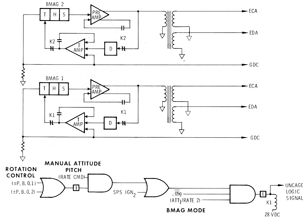
Gyro Assembly - 2 (GA - 2)
GA - 2 contains three BMAGs that are always rate caged.
These BMAGs normally provide pitch, yaw, and roll rate damping for SGS
automatic control configuration and proportional rate maneuvering. The
rate signals interface with the ECA. When backup rate by axis is selected
(RATE 1), the GA-2 signal(s) is not used.
Rotational Controllers (RC - 1 and RC -2)
The RCs provides the capability of controlling the
spacecraft attitude simultaneously in three axes. Either controller
provides the functions listed below for each axis (pitch, yaw, roll) and
for each direction of rotation (plus or minus).
Within the RC are six breakout switches, three
transducers, and twelve direct switches. (See
Rotation Control Interfaces
Schematic.)
A breakout switch, closed at a nominal 1 .5 degree RC
deflection, routes a 28-vdc logic signal to both the PGNCS and the SCS for
attitude control inputs as follows:
a.
Rotation Command to CMC. If the
spacecraft is under CMG control, the signal commands rotations through the
CMG input to the RJ /EC.
b.
Acceleration Command. The signal
is sent to the RJ/EC and commands rotational acceleration whether in CMG
or SCS control.
c.
Minimum Impulse Command. If the
spacecraft is under SCS control, the logic signal goes to the ECA which
provides a single minimum impulse command to the RJ /EC each time that a
breakout switch is closed.
d.
Proportional Rate Enable. The
logic signal is used in the EGA to enable the manual proportional rate
capability and to rate cage the BMAGs in GA - 1.
The transducer is used for proportional rate maneuvers.
It provides a signal to the EGA that is proportional to the stick
deflection. The signal is summed in the ECA with the rate BMAG signal in
such a way that the final spacecraft rate is proportional to the stick
(RC) deflection.
At 11 degrees of controller deflection a direct switch
closes. If direct power is enabled, the direct switches route 28 vdc to
the direct coils on the appropriate RCS engines and disable the auto coil
solenoid drivers in that axis (or axes).
The translation controller provides the capability of
manually commanding simultaneous accelerations along the spacecraft X-,
Y-, and Z-axes. (See Translation Control Interfaces
Schematics) It is also used to initiate several transfer
commands. These functions ar5e described below.
Translation Control
Interfaces Schematics
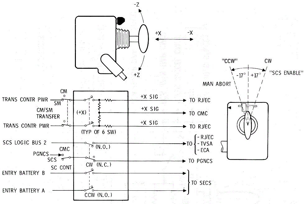
a.
CMG Control. If the spacecraft is
under CMC control, a translation command results in a logic signal ( 28
vdc) being sent to the CMG. The CMC would provide a translation command to
the RJ /EC.
b.
SGS Control. If the spacecraft is
under SCS control, the translation command is sent to the RJ /EC.
Clockwise Switches
(CW).
A clockwise rotation of the T-handle will disable CMC
inputs to the RJ /EC. A logic signal (CW) is sent to the CMC when the
T-handle is at null.
Counterclockwise
Switch (CCW).
A
counterclockwise rotation of the T-handle during launch, will close
switches which route 28 vdc (battery) power) to the MESC. Th e MESC, in
turn, may enable the RCS auto coil solenoid drivers in the RJ /EC.
Electronics Control
Assembly (ECA)
The ECA contains the electronics used for SCS automatic
attitude hold, proportional rate, and minimum impulse capabilities. It
also contains the attitude BMAG(s) uncage logic. It receives control
inputs from the gyro assemblies and the rotational controller- transducers
and breakout switches (MIN IMP). The ECA provides rotational control
co1nmands to the RCS logic in the RJ /EC.
Reaction Jet Engine Control (RJ/EC)
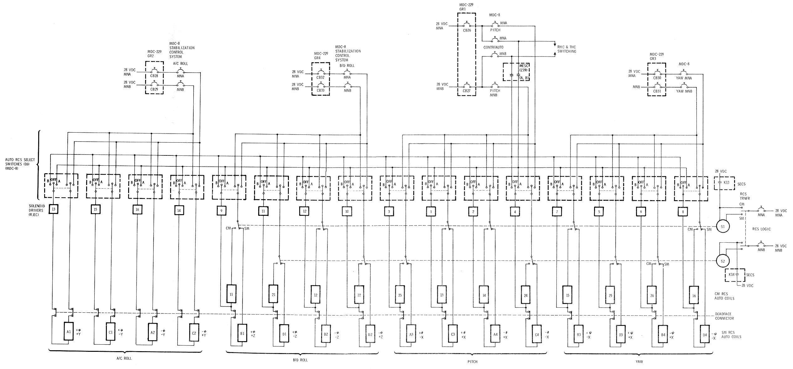
The RJ/EC contains the auto RCS logic and the solenoid
drivers (16) that provide commands to the RCS automatic coils. The auto
RCS logic receives control signals from the CMC, ECA, RC, and TC. The RCS
solenoid drivers receive enabling logic power from the AUTO RCS SELECT
switches on MPC - 8. The MESC supplies the 28 vdc to the AUTO RCS SELECT
switches (Auto
RCS Enabling Power Schematic)
Auto RCS Enabling
Power Schematic
Reaction Control Subsystem Interface
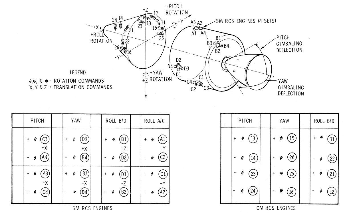
The RCS provide s the rotation control torques and
translation thrusts for all ACS functions. Prior to CM/SM separation, the
SM RCS engines are used for attitude control. The CM RCS is used after
separation for control during entry (SM
Jet Functions Diagram
and Auto
RCS Enabling Power Schematic). The CM has only 12 RCS engines
and does not have translational capability via the TC. After CM/SM
separation, the A/CROLL AUTO RCS SELECT switches have no function, as the
12 CM engine s need only 12 AUTO RCS SELECT switches (Auto RCS Enabling Power Schematic).
An RCS engine is fired by applying excitation to a pair
{fuel and oxidizer) of solenoid coils; the pair will be referred to in the
singular as a solenoid coil. Each engine has two solenoid coils. One coil
is referred to as the automatic coil, the other as the direct coil. Only
the automatic coils receive commands from the RJ / EC. The direct commands
are routed directly from the RC direct switches (or other switches). The
automatic and direct commands are discussed in the following paragraphs.
The automatic (auto) coils are supplied 28-vdc power
via one set of contacts of the AUTO RCS SELECT switches (Auto RCS Enabling Power Schematic).
The solenoid is operated by switching a ground to the coil through the
appropriate solenoid driver in the RJ /EC. T h e auto coil power is
obtained from the STABILIZATION/CONTROL SYSTEM A/C ROLL, B/D ROLL, PITCH
and YAW circuit breakers on panel 8. The 28 vdc lines to the auto coils on
SM engines (jets) except A1, A2, C1, and C2 are switched at CM/SM transfer
to CM coils. The wires from the A/C ROLL AUTO RCS SELECT switches to SM
engines A 1, A2, C1, and C2 are open-ended after transfer. These switches
have no function for the CM configuration. Enabling power for the RCS
solenoid drivers is supplied to the second set of contacts of the AUTO RCS
SELECT switches through the MESC (A and B) from the SCS CONTR/AUTO MNA and
MNB circuit breakers (MDC-8).
The CM jets are supplied from two separate propellant
systems, 1 and 2. The jets are designated by the propellant system. Each
propellant system supplies half the CM jets, distributed such that one jet
for each direction (plus and minus) and for each axis (pitch, yaw, and
roll) is supplied from the 1 system and the other from the 2 system. When
the RCS TRNFR switch is placed from SM to CM, motor switch contacts
transfer auto coil power from SM engines to CM engines. Each motor switch
contact transfers six engines.
Auto RCS Logic.
Commands to the RCS engines are initiated by switching
a ground, through the solenoid driver, to the low voltage side of the auto
coils. The solenoid drivers receive commands from the auto RCS logic
circuitry contained in the RJ /EC. The auto RCS logic performs two
functions:
a.
Enables the command source
selected based on logic signals received from the control panel 01' manual
controls.
b.
Commands those solenoid drivers
necessary to perform the desired maneuver.
The logic receives RCS commands from the following
sources:
·
CMG (provides rotational and
translational commands).
·
EGA (provides rotational commands
for either automatic attitude hold, proportional rate, or minimum impulse
control).
·
RC-1 and/or RC-2 (breakout
sw1tches (BO) provide continuous rotational acceleration).
·
TC (provides transIational
acceleration commands).
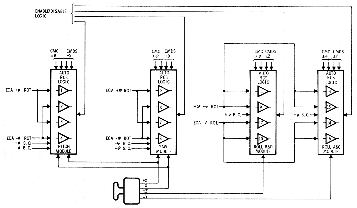
The auto RCS logic (Auto
RCS Signal Flow Schematic) is represented by four modules: one
module each for pitch and yaw and two for roll (B /D and A /C). The
solenoid drivers (four) associated with each module (shown as numbered
triangles) correspond to the RCS engine solenoid drivers. The command
sources (listed above) are shown as separate inputs to the modules, while
enable/ disable logic is represented as a single line to each module.
Auto RCS Signal
Flow Schematic
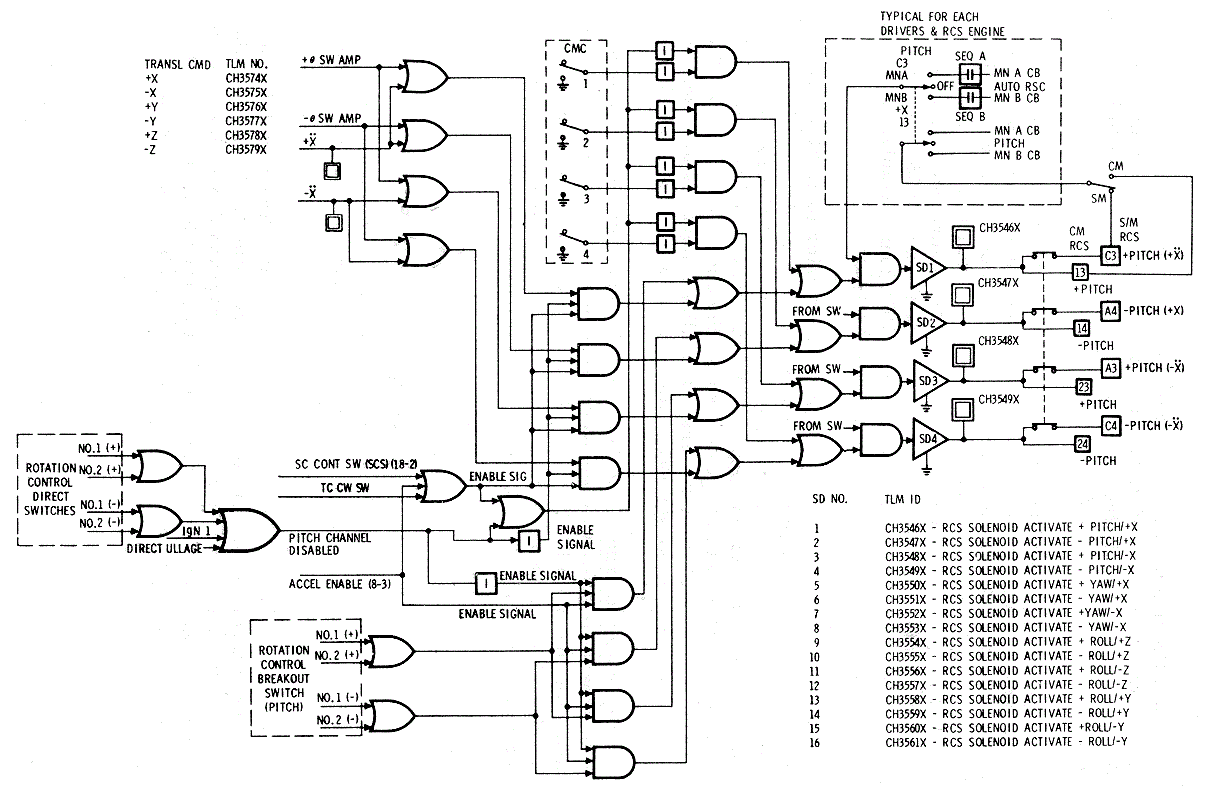
A detailed functional drawing of the pitch auto RCS
logic shows how the command priorities are mechanized in the RJ/EC. (See Auto
RCS Logic Schematic)
Direct
Coil Commands.
At the initiation of direct coil commands, all command
input channels to the auto RCS logic module(s) in that axis (axes) are
inhibited. Pitch and yaw auto con1.1nand s are inhibited during SPS
thrusting (IGN 1). This prevents auto coil commands from firing the RCS
during SPS thrusting.
If a MANUAL ATTITUDE switch(es) is placed in the ACCEL
CMD position, the CMC and ECA inputs to the auto RCS logic module(s) in
that axis (axes) are inhibited. Commands to fire auto coils are enabled
from the RC breakout switches. (See bottom "and" gates in
Auto RCS Logic Schematic)
The ECA inputs to the auto RCS logic modules (SM Jet Functions Diagram)
provide both the 1ninimum impulse commands, as well as automatic attitude
hold, automatic rate damping, and proportional rate co1n1nand. When MIN
IMP is selected on a MANUAL ATITUDE switch, the EGA is configured to
accept RC breakout commands and supply output pulses. All other outputs of
the EGA are inhibited in the EGA.
The RCS engines can be operated by applying 28 vdc to
the direct coils, as the other side of the direct coils is hard wired to
ground. The coils receive commands from the sources described in the
following paragraphs (shown in
Direct Control Loop Schematic).
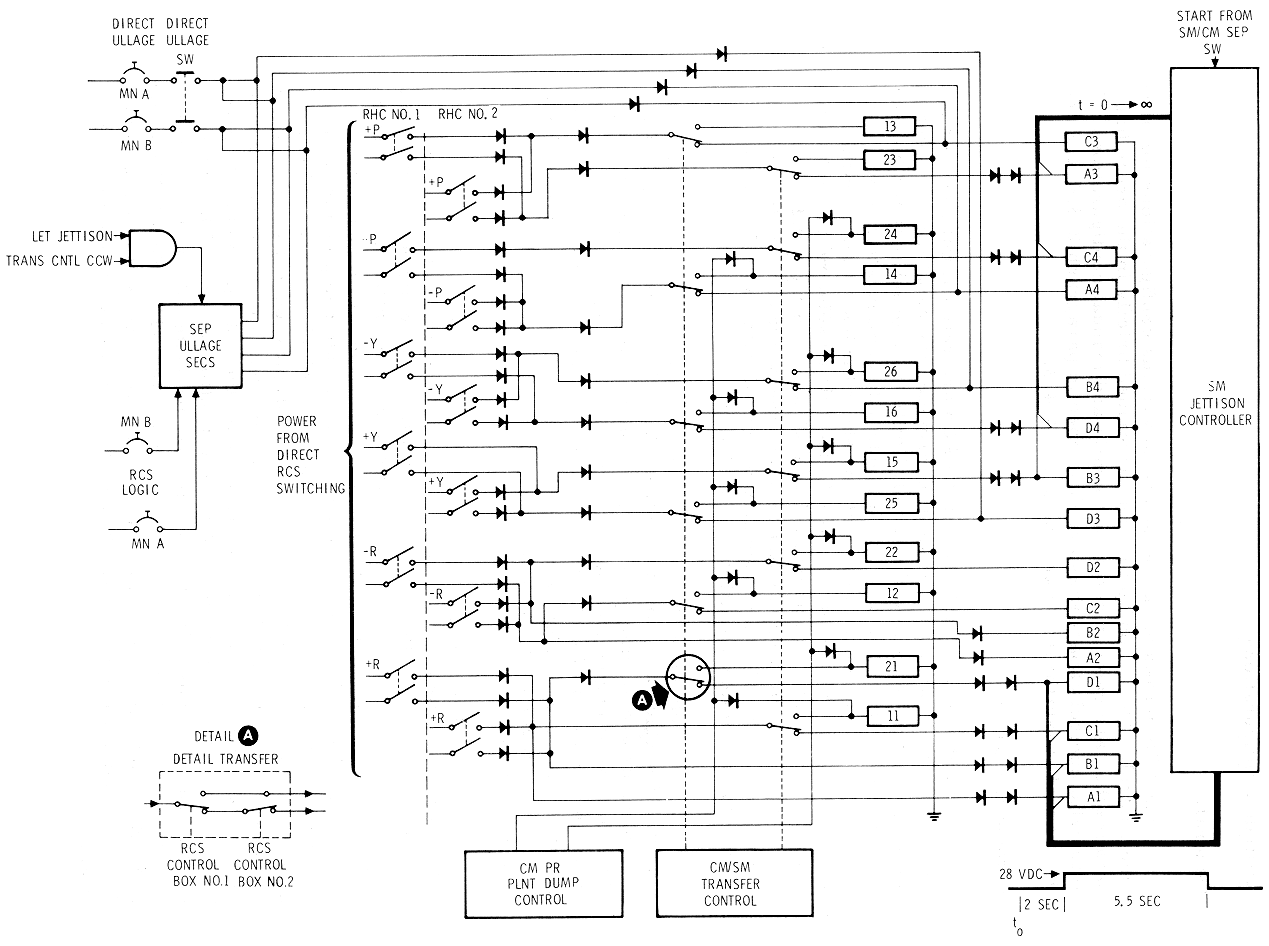
The direct switches in the rotation controllers (RCs)
are enabled when the ROT CONTR PWR-DIRECT 1 & 2 switches on MDC - 1
are up or down. The RCS commands are initiated when the RC is deflected a
nominal 11 degrees about one or
more of its axes. At this displacement a switch (direct) closure occurs,
routing 28 vdc to the appropriate direct coils and to the auto RCS logic (Automatic
Coil Commands). The signal to the auto RCS logic disables the
solenoid drivers in the channel(s) under direct control.
An ullage is performed prior to an SPS thrust maneuver.
Direct ullage is a backup to TC +X translation. Pressing the DIRECT ULLAGE
pushbutton routes 28 vdc to the SM direct coils on the pitch and yaw RCS
engines used for +X translations. (See SM
Jet Functions Diagram) A signal (28 vdc) is sent to the auto
RCS logic that disables the pitch and yaw solenoid drivers. The ullage
signal is also sent to the SPS ignition logic in the RJ/E.C. (Manual
Thrust Vector Control
The SECS (MESC)
can command an ullage to enable separation of the CSM spacecraft from the
S-IVB adapter. The ullage uses the same RCS engines as the direct ullage
command and disables the pitch and yaw solenoid drivers. The enabling
logic for this function is shown in SM
Jet Functions Diagram
The SM JETTISON CONTROLLER sends commands to SM direct
coils for -X translation and +roll rotation.
CM PROPELLANT
JETT-DUMP Control
This function is used after the RCS capability is no
longer required. Actuation of the CM PROPELLANT DUMP switches will provide
commands to the direct coils on all CM engines, except 13 and 23.
At CM-SM separation the lines from the RC direct
switches are transferred from SM direct coils to CM direct coils. This is
similar to the automatic coil transfer described in paragraph
Automatic Coil Commands,
except that either of the two transfer motors transfers power to all CM
direct coils. The lines for direct or separation ullage (steps b and c),
are open ended at CM-SM separation.
The SCS hardware can be placed in various
configurations for attitude control. These configurations, described
briefly in the preceding paragraphs, are categorized as automatic and
manual configurations. The automatic control capabilities are described in
Automatic
Coil Commands and
the manual capabilities in Direct
Coil Commands.
The automatic capabilities of the ACS are rate damping
and attitude hold. The rate damping configuration provides the capability
of r educing large spacecraft rates to within small limits (rate deadband)
and holding the rate within these limits. The attitude hold configuration
provides the capability of keeping angular deviations about the body axes
to within certain limits (attitude deadband). If attitude hold is selected
in pitch, yaw, and roll, the control can be defined as maintaining a fixed
inertial reference. The rate damping function is used together with the
attitude hold configuration; therefore, the description of the rate
control loop is included in the following attitude hold discussion.
Attitude hold uses the control signals provided by the
rate and attitude BMAGs which are summed in the ECA. (See
SCS Attitude and Thrust Vector
Control System Schematic.) The control loops are summed at the
input to a switching amplifier which provides the on-off engine commands
to the auto RCS logic. E ach of the three switching amplifiers (pitch,
yaw, and roll) has two outputs that provide clockwise and counterclockwise
rotation commands. The polarity of the d-c input voltages to the switching
amplifiers determines the commanded direction of rotation.
SCS Attitude and
Thrust Vector Control System Schematics
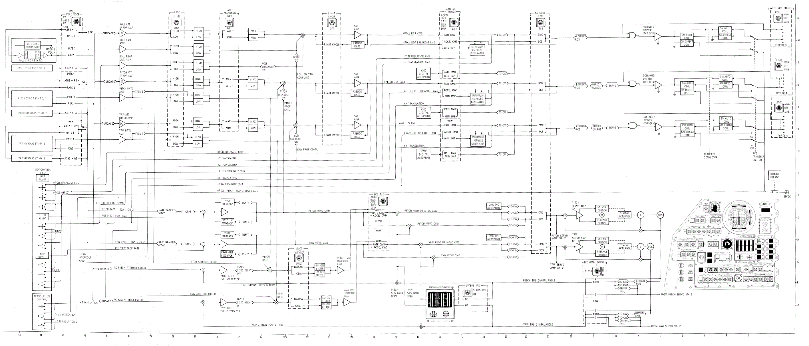
If the switching amplifier input signal is smaller than
a specific value, neither output is obtained. This input threshold
required to obtain an output is the switching amplifier deadband.
Manually-selectable gain authority provides flexibility in the selection
of the attitude hold deadband width, the rate damping sensitivity and
proportional r ate command authority. The RATE switch controls both the
rate damping threshold and the proportional rate command authority, which
is discussed in paragraphs to follow. Since the attitude hold
configuration utilizes the attitude and r ate loops, the switching
arr1plifiers will switch on when the summation of attitt1de err or and
rate signals equals the voltage deadband. Attitude error signals are
scaled (20:1) as a function of the RATE switch. In addition, a deadband
limiter circuit may be switched into the attitude error loops. This is
accomplished by having the ATT DEADBAND switch in MAX, which, in effect,
blocks the first four degrees of attitude error. The rate and attitude
error deadbands are summarized in the following table.
Attitude Deadband
Switch Position Table

During attitude hold it is desirable to maintain
minimum rotation rates to conserve propellants. This capability is
provided by the pseudo-rate circuit. Pseudo-rate feedback around the
switching amplifier is enabled via the LIMIT CYCLE switch. Placing the
LIMIT CYCLE up causes the switching amplifier output to pulse off and .on
when the input level approaches the threshold.
When the pseudo-rate mode is used, the pulse duration
from the switching amplifier may be insufficient to insure proper
operation of the solenoid valves in the RCS. This applies for operation
near the deadband limits. To insure a sufficiently-long pulse to the
solenoids, a one-shot circuit is connected downstream from the switching
amplifier. The one shot provides a single minimum-impulse command
(on-time) for each switching amplifier output pulse. When the switching
amplifier pulse width exceeds the one shot on-time, the longer RCS command
is initiated. The output pulse width of the one shot is a function of the
d-c bus voltage; the pulse width increases as the bus voltage decreases.
This is because the solenoid valve pickup time increases as the bus
voltage decreases; therefore, a longer RCS "on" command is required. Thus,
the one-shot circuit provides compensation for bus voltage variations: the
pulse width varies approximately from 13 msec to 17 msec over a bus
voltage range of 30 to 25 vdc. The one-shot circuit is also used in manual
minimum impulse control. This configuration is described in the next
paragraph.
An additional rate control loop is used for the yaw
axis only. This loop is enabled during entry, after .05 G, and is used to
cancel unwanted yaw rate BMAG signals. The unwanted yaw BMAG signals are
those signals resulting from roll maneuvers about the stability X-axis.
The 21-degree offset between this axis and the X-axis causes the yaw BMAG
to sense a component of the entry roll rate.
Following are the manual attitude control capabilities.
·
DIRECT
·
ACCELERATION CMD
·
MINIMUM IMPULSE
·
PROPORTIONAL RATE
The commands listed are initiated by manual inputs to
either rotation controller with the exception of direct, the RC commands
rotations through the RCS auto coils.
The manual rotation control capabilities are discussed
further in the following paragraphs.
Proportional rate provides the capability to command
spacecraft rates that are proportional to the RC deflection. The RC
transducer output is summed (by axis) through the breakout switch logic
path (SCS
Attitude and Thrust Vector Control System Schematic) with the
rate signal from the BMAG. Initially, the RC output (commanded rate) will
be larger than the BMA G output (actual rate) so that the summed signals
will be greater than the switching amplifier threshold. The RCS engines
will fire until the summation of the r ate and commanded rates are within
the switching amplifier deadband. When the RCS engines stop firing, the
spacecraft will continue to rotate at a constant rate until a new r ate is
commanded.
Since the MANUAL ATTITUDE switch must be in RATE CMD
for proportional rate, the spacecraft will be under automatic control when
the RC is released.
The rate commanded by a constant stick deflection is a
function of the ratio of the control loop gains. The ratio has two
possible values which are selected by the RATE switch. The nominal rate
commanded at maximum stick deflection (soft stop), for both rate switch
positions, are I shown in the following list.
The switching chart shows the LIMIT CYCLE switch in the
OFF position. Performing a proportional rate maneuver with pseudo-rate
enabled (switch-on), required more RCS fuel than the same maneuver without
pseudo -rate feedback.
Minimum impulse
provides the capability of making small changes in the spacecraft rate.
When minimum impulse is enabled, the switching amplifier output is
inhibited. Thus, the spacecraft (attitude) is in free drift in the axis
where minimum impulse is enabled, if direct control is not being used.
Minimum impulse control is commanded by the RC break
out switch. This switch provides a 28-vdc logic signal to the one-shot
circuit in the EGA. The one shot (Automatic
Control) provides a command to the auto RCS logic for a
nominal 15 ms. Additional minimum impulse commands are obtained each time
a breakout switch is closed (by repeated opening and c losing of the
breakout switch).
When acceleration command is enabled and a -breakout
switch is closed, continuous commands are sent to the appropriate RCS auto
coils. The SC CONT switch has no function in enabling the acceleration
command capability, which is second in priority only to direct coil
operations. (Refer to
Automatic Coil Commands)
Direct control is similar to acceleration command
except that the direct RCS coils are used. Also, instead of a breakout
switch providing the firing command, the RC direct switch is used to
provide 28 vdc straight to the direct coils (SCS Attitude and Thrust Vector
Control System Schematic). Power to the RC direct switches is
controlled by the two ROT CONTR PWR DIRECT switches on MDC-1, one switch
controlling the 28 vdc for each RC. (See
SCS D-C Power Distribution
Schematic.) During direct control in an axis, all auto coil
commands i n that axis are inhibited in the auto RCS logic (Auto RCS Logic Schematic).
CS D-C Power
Distribution Schematic


When power is supplied to the translation control (TC),
a manual translational command fires auto coils to give acceleration(s)
along an axis (or axes). The TRANS CONTR PWR switch on MDC -1 supplies 28
vdc to the T C translational switches (SCS D-C Power Distribution
Schematic).
TC inputs are routed as logic inputs to the auto RCS
logic when the spacecraft i s under SCS control. However, during CMG
control, TC commands arrive at the auto RCS logic via the CMG. (Auto RCS Logic Schematic)
Since the TC uses only SM RCS engines, after CM/SM separation the T C has
no translation function.
Other translational control is possible from inputs
other than the TC. These are direct ullage, CSM/LV separation ullage, and
CM/ SM minus -X I translation (SM JETT CONT). These translation commands
utilize direct coils. (See Direct
Control Loop Schematic)
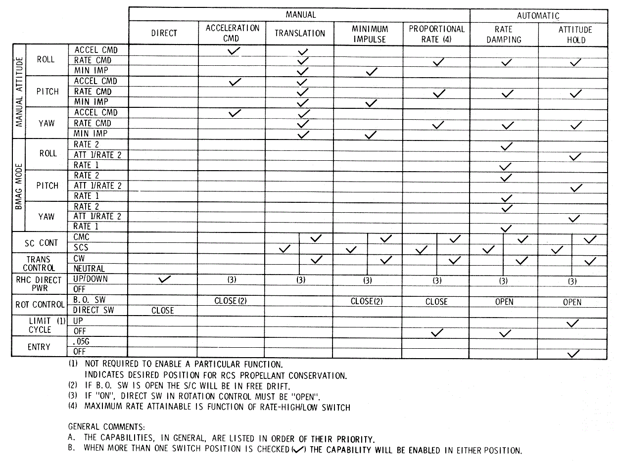
Certain panel switch combinations are necessary for
each ACS capability that has been discussed. For a summary, see
ACS Control Capabilities
Diagram
ACS
Control Capabilities Diagram
THRUST VECTOR CONTROL (TVC)
The spacecraft attitude is controlled during a delta V
by positioning the engine gimbals (TVC) for pitch and yaw control while
maintaining roll attitude with the attitude control subsystem. The SCS
electronics can be configured to accept attitude sensor inputs for
automatic control (SCS auto TVC) or rotational controller (RC) inputs for
manual thrust vector control (MTVC). Manual TVC can be selected to utilize
vehicle rate feedback signal s summed with the manual inputs; this
comprises the MTVC /RATE CMD configuration. Selecting MTVC without rate
feedback describes the MTVC/ACCEL CMD configuration. A different
configuration can be selected for each axis; for example, one axis can be
controlled manually while the other is controlled automatically.
The following paragraphs present the characteristics of
the SCS/TVC configurations. A switching table, specifying the panel
switching and logic signals required for enabling each configuration, is
included. The operation of the engine ignition/thrust on- off logic is
also described.
On the simplified TVC signal flow diagram shown in the
TVC
Signal Flow Schematic functional enabling switches are used
for reference. The TVC switching table (TVC
Switching Table) relates the functional switching and panel
switching to the TVC configuration desired. Both figures are applicable to
either the pitch or yaw TVC channel.
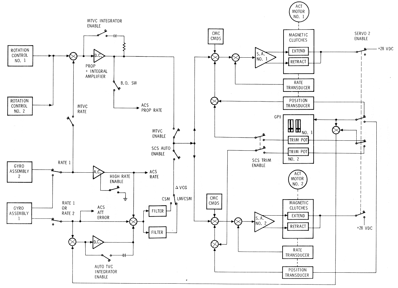

In general, it is possible to enable a functional
switch through several (alternate) panel configurations. The alternate
configurations usually require the CW logic signal which is obtained from
a clockwise rotation of the translation controller (TC) T -handle. This
provides a convenient means of transfer ring from one TVC configuration to
another during tl1e thrusting maneuver. The CW signal will also enable
transfer from servo No. l to servo No. 2 (TVC Switching Table)
under certain conditions. Thus, it is possible to transfer to a completely
redundant configuration by using the TC clockwise switch.
The gimbal servo control loop consists of a servoamp
that drives two magnetic clutch coils; one coil extends the actuator; the
other retracts the actuator. Gimbal rate and position transducers provide
feedback for closed loop control. Two servo control channels are provided
in each axis, pitch and yaw. The active channel is selected through
functional s witch servo 2 enable (TVC
Signal Flow Schematic). Primary control utilizes servo No. 1.
Servo No. 2, in an axis, can be engaged either by selecting 2 position on
the TVC GMBL DR switch or by automatic transfer. Automatic transfer will
occur, if the TVC GMBL DR switch is in the AUTO position and either the FS
(fail sense) or CW logic signal is present. The CW logic will enable
transfer to servo No. 2 in both axes, whereas, the FS logic will enable
transfer only in the axis where i t is present. The fail sense signal is
generated in tl1e motor excitation circuitry of servoactuator No. 1,
occurring when an overcurrent is sensed. The transfer logic described is
included in the switching table (TVC
Switching Table).
The gimbal position display (Gimbal Position and Fuel Pressure
Indicator Diagram) is used as a monitor of SPS pitch and yaw
gimbal deflections from actuator null during CMC and SCS control of a
delta V. Prior to an SCS Delta V, the SPS engine must be positioned with
the trim thumbwheels on the GPI. In this case, the GPI will display the
trim gimbal angles that are set with the thumbwheels.
Since there is only one display panel of gimbal
position, there are redundant indicators, servometric meter drivers, and
power supplies associated with both the pitch and yaw position displays.
(See GPI
Signal Flow Schematic.)
When servo channel No. 1 is controlling the SPS actuator, the position
input to both GPI indicators (pitch and yaw) is supplied from the No. 1
position transducer. If actuator control is transferred to the No. 2
servo, then the No. 2 position transducer drives both indicators in that
axis. If the FDAI/GPI P OWER switch is in BOTH position then all four
indicators are powered. With the switch in position 1, the first and third
indicators are enabled. The second and fourth indicators are energized
with the switch in position 2.

In order to configure the SCS electronics for an SCS
auto TVC, certain panel switches must be positioned. In addition, other
manual or automatic logic switching will affect the control signals and
servo loops.
Since SCS auto TVC requires attitude error signals from
GA-1, the gyro uncage logic must be satisfied (BMAG Logic and Outputs Schematic).
This requires that the BMAG MODE switches be in ATT 1 RATE 2, the ENTRY -.
05 G switch be OFF, and that the SPS ignition signal (IGN 2) be present.
For attitude hold (Gyro
Assembly - 1), the IGN 2 logic was not needed as GA-1 can be
uncaged by placing the MANUAL A TTITUDE switches to RATE CMD while having
no breakout switch input.
The attitude error signal (in pitch and yaw) i s summed
with the SPS gimbal position and GPI trim at the input to an integrator (TVC
Switching Table). The integrator output is summed with
attitude error and rate, filtered for body-bending, and then applied as an
input to the servo amplifiers (primary and secondary). During a delta V
the integrator output insures that the thrust vector stays inertially
fixed even though the cg shifts as the propellants are consumed. The
signal path requires that the delta V is under SCS control with the SCS
TVC switch in AUTO.
Though the control signal is applied to both servo
amplifiers, only one will be positioning the SPS gimbal actuators.
Selection logic controlling which servo amplifier is energized is
represented by the SERVO 2 ENABL E functional switch. The TVC GIMBAL DRIVE
switches on MDC - 1 have AUTO positions which provide an automatic
transfer from servo 1 to servo 2 if either a TC-CW switch is closed or an
over-current logic signal is sent from the SPS. Positioning the TVC GIMBAL
DRIVE switches to 1 or 2 selects the desired servo loop, but overrides the
T C -CW or over-current transfer.
Pre-thrust gimbal trim is accomplished by manually
turning the trim wheels on the gimbal position indicator (GPI) to obtain
the desired indicator readout. The trim wheel in each axis is mechanically
connected to two potentiometers. As shown in
TVC Signal Flow Schematic,
one potentiometer is associated with servo No. 1 and the second with servo
No. 2. It is desirable to pretrim before an SCS delta V, to minimize the
transient duration I and the accompanying quadrature accelerations. It is
also desirable to set the trim wheels properly before a CMC delta V if the
SCS AUTO configuration is to serve as a backup. This will enable the SCS
to relocate the desired thrust direction if a transfer is required after
engine ignition.
Manual control of the thrust vector utilizes crew
commands via the RC to position the gimbaled SPS. There are two types of
MTVC: M T VC with rate damping (rate command) and MTVC without rate
damping (acceleration command). Either mode of MTVC is selectable by panel
switching. In addition, TC-CW logic provides either an automatic transfer
from a PGNCS-controlled delta V or from an SCS auto delta V. (TVC Switching Table)
In order to provide ease of manual control, a
proportional plus integral amplifier is incorporated in the MTVC signal
flow path. The operation of this circuit can be described by considering
the response to a step input; the output will initially assume a value
determined by the proportional gain and the input amplitude. It will then
increase, from this value, as a straight-line function of time. The slope
of the line is a function of the input amplitude and the integrator
constant. When the input is removed, the output will then drop by the
initial value. With no additional inputs the output will theoretically
remain constant (in practice, it will slowly decay). The circuit
(integrator) provides the following capabilities:
a.
Maintain a gimbal deflection
after returning the RC to rest.
b.
Make corrections with the RC
about its rest position, rather than holding a large displacement.
c.
With no manual inputs, SC r ate
is damped out in the RATE CMD configuration.
The selection between the RA TE CMD and ACCEL CMD
configurations is made by enabling rate signals in the RATE CMD mode with
the IGN 2 logic signal p resent (thrust on). This enables rate BMAG
signals to be summed with RC inputs. The position of the BMAG MODE switch
determines which rate source (BMAG 1 or 2) is summed, through its
associated functional switch. Placing the SCS TVC switch in the ACCEL CMD
position disables the rate command mode.
The RATE CMD configuration is analogous to the
proportional rate capability described in the ACS (ATTITUDE CONTROL SUBSYSTEM)
except there is no deadband. With no manual input, the thrust vector is
under rate BMAG control. If there is an initial gimbal cg misalignment, an
angular acceleration will develop. The rate BMAG, through the proportional
gain, will drive the gimbal in the direction necessary to cancel this
acceleration. With no integrator, a steady-state rate would be required to
hold the necessary gimbal deflection (through cg). However, due to the
integrator, the rate is driven to zero. When an RC input (manual) is
present, a steady-state vehicle rate will be established so that the
integrator input goes to zero when the output value is sufficient to place
the thrust vector through the c g. When the manual input is removed the
rate is driven to zero.
When rate feedback is inhibited by selecting ACCEL CMD,
the RC input must be properly trimmed to position the thrust vector
through the cg. However, positioning the thrust vector through the cg only
drives the rotational acceleration to zero. Additional adjustments (RC
trimming) are necessary to cancel residual rates and obtain the desired
attitude and positioning vector.
Engine Ignition, Thrust On- Off Logic
This section describes the configurations available for
ignition on- off control. Panel switch positions and/or logic signals
necessary for a particular configuration are considered. The functions of
outpt1t (logic) signals are given.
Redundant d-c power is supplied to redundant SPS coils
and solenoid drivers (as shown in the
Engine Ignition-Thrust On-Off
Logic Schematic) via the delta V THRUS1- (A and B) switches.
Engine
Ignition-Thrust On-Off Logic Schematic

With the switch positions shown in the
Engine Ignition-Thrust On-Off
Logic Schematic, engine ignition is commanded by placing a
ground on the low side of SPS coil No. 1. Thrustoff is commanded when the
ground is removed. The ground switching can be accomplished in two basic
ways. One method is to position the SPS THRUST switch from the NORl'v1AL
to the DIRECT ON position for engine turn-on, and later placing the delta
V T HRUST A and B from NORMAL to OFF to terminate thrust. The second
method is to switch the ground through the solenoid driver as commanded by
the thrust on-off logic.
Engine ignition will be commanded by the thrust on- off
logic when any one of the thrust-on logic equations shown in the
Engine Ignition-Thrust On-Off
Logic Schematic is
satisfied. The CMC commands thrust-on (equation 1) by supplying a logic 0
to the thrust on-off logic when the SC CONT switch is in the Civ1C
position and the translation controller (TC) is not clockwise (CW).
When the CMC changes the logic signal from a 0 to a 1, thrust-off is
commanded.
For the SGS control configuration the SC CONT sw must
in the SC S position or the TC handle clockwise (CW). A thrust - on
enabling signal is obtained from the EMS/ delta V display. Thrust-on is
then commanded by commanding a +X-axis acceleration and pressing the T
HRUST ON pushbutton. When the ground to the SPS coil has been sensed by
the ignition sense logic, the THRUST ON and +X -axis commands can be
removed and engine ignition will be maintained by the SPS latch up signal.
When the delta V counter on the entry monitor system (EMS) display reads
zero, the EMS enabling signal is removed and thrust-off is commanded.
If TVC control is transferred from the CMC to the SCS
(by SC CONT switch to SCS or TC to CW) after engine ignition, thrusting
will be maintained by the presence of the SCS latch up signal. Thrust-off
will be commanded as in a normal SCS control configuration. A backup
thrust-off command, for any control configuration, is obtained by placing
the 6,.V T HRUST (A and B) switches to the OFF position.
The +X logic signal which is necessary to enable
thrust-on in the SCS configuration, can be obtained from either the DIRECT
ULLAGE pushbutton or the TC +X contacts. The difference between the two
commands are:
a.
Direct ullage uses the direct
coils and inhibits the pitch and yaw solenoid drivers; thus, attitude hold
cannot be maintained in these axes. Ullage-ignition overlap time is
completely under manual control.
b.
When commanding A+X with the T-C,
attitude hold can be maintained. Ullage-ignition overlap time is
automatically limited to one second.
The circuitry provides several output functions. A
ground is provided for the SPS THRUST lamp on the EMS display. The ground
is also sensed by the ignition sense logic, which generates signals for
both disabling the RCS pitch and yaw auto commands and also for
configuring the SCS electronics for thrust vector control.
The RCS disabling signal, IGN 1 on the
Engine Ignition-Thrust On-Off
Logic Schematic, is not present until one second after engine
ignition and is not removed until one second after engine turn- off. This
provides adequate time for engine thrust buildup and decay. The IGN 2
logic signal is required in the logic for the functional switches in the
SCS-TVC signal flow paths. There are separate IGN 2 signals generated for
SCS auto TVC and for MTVC. These signals are generated at the same time
the ground is switched to the SPS coil, but are not removed until one
second after the ground· is removed. The delayed OFF enables the TVC
electronics to maintain spacecraft control during thrust decay.
The SCS circuit breakers (panel 8) supply electrical
power to both panels 1 and 7 power switches and also to the SCS panel 1
switches for logic signals. The panel 7 SCS switches distribute a-c and
d-c power to the SCS hardware (SCS D-C Power Distribution
Schematic) and route the SCS logic bus power to panel 1
switches. (SCS
D-C Power Distribution Schematic) The power switching for the
two rotation hand controllers and the translation hand controller is on
panel 1. (See SCS
D-C Power Distribution Schematic.)
The SCS performance data is included in the CSM
Spacecraft Operational Data Book (SNA-8-D- 2 7). For the SCS operational
limitations and restrictions refer to AOH, Volume 2, including the
Malfunction Procedures.
The entry monitor system (EMS) provides a visual
monitor of automatic primary guidance navigation and control system
(PGNCS) entries and delta velocity maneuvers. The EMS also provides
sufficient display data to permit manual entries in the event of PGNCS
malfunctions together with a command sent to the SCS for SPS engine
cutoff. The delta velocity display can also be used as the cue to initiate
manual thrust-off commands if the automatic-off commands malfunction.
During rendezvous the EMS provides a display of VHF ranging information.
Self- test provisions are provided by a function switch
for the three operational modes (entry, delta V, and VHF ranging) to
provide maximum system confidence prior to actual use.
The EMS performance data is included in the CSM
Spacecraft Operational Data Book (SNA- 8- D- 27). For the E MS operational
limitations and restrictions refer to AOH, Volume 2, including the
Malfunction Procedures.
The EMS provides five displays and/ or indications that
are used to monitor an automatic entry or to aid in performing a manual
entry.
The threshold indicator, labeled. 0 5 G, illuminate s
when the atmospheric deceleration is sensed. The altitude a t which this
indicator is illuminated is a function of the entry angle (velocity vector
with respect to local horizontal), the magnitude of the velocity vector,
geographic location and heading, and atmospheric conditions. Bias
comparator circuits and timers (EMS
Block Diagram) are used to initiate this indicator. The signal
used to illuminate the indicator is also used internal to the EMS to start
the corridor evaluation timer, scroll velocity drive, and range- to-go
circuits.

The roll stability indicator (RSI) provides an
indication of lift vector position throughout entry. With the ATT SET
switch in the GDC position, the RSI will be aligned prior to 0. 05G by
rotating the yaw thumbwheel on the attitude set control panel with the EMS
ROLL switch in the entry position while pressing the GDC A LIGN button.
During entry, stability axis roll attitude will be supplied to the RSI by
the gyro display coupler. There are no degree markings on the display, but
the equivalent readout will be zero I when the RSI points toward the top
of the control panel. During the entry RSI rotates in the opposite
direction to the spacecraft roll.
Corridor Verification Indicators
The corridor verification indicators are located above
and below the RSI. They consist of two lights which indicate the necessity
for lift vector up or down for a controlled entry. The indicators will be
valid only for vehicles which utilize lunar entry velocities
(approximately 35, 000 FPS) and entry angles. The corridor comparison test
is performed approximately 10 seconds after the .05 G indicator is
illuminated. The lift vector up light (top of RSI) indicates 11G 11
greater than approximately 0. 262G. The lift vector down light (bottom of
RSI) indicates "G" less than approximately 0. 262G. EMS Corridor Evaluation Diagram is
a typical example of the corridor evaluation function. An entry angle is
the angular displacement of the CM velocity vector with respect to local
horizontal at 0. 05G, The magnitude of the entry angles that determines
the capture and undershoot boundaries will be a function of CM
lift-to-drag (L/D) ratio. The angles shown are for a L/D of 0. 3 to 0. 4.
The EMS positive lift overshoot boundary is that entry angle that produces
approximately 0. 262G at approximately 10 seconds after the .05 G
indicator is illuminated. An entry angle greater than the EMS positive
lift overshoot boundary will cause the upper corridor verification light
to be illuminated. Conversely, an entry angle less than the positive
overshoot boundary will light the lower corridor light. Entry angles less
than the capture boundary will result in noncapture regardless of lift
orientation. Noncapture would result in an elliptical orbit which will
re-enter when perigee is again approached. The critical nature of this
would depend on CM consumables: power, control propellant, life support,
etc. The command module and crew will undergo excessive Gs (greater than
10G) with an entry angle greater than the undershoot boundary, regardless
of lift orientation.
EMS Corridor
Evaluation Diagram

Delta V /Range-To-Go Indicator
The delta V /range-to-go indicator is an electronic
numeric readout which has three functions. During entry the inertial
flight path distance in nautical miles to predicted splashdown after 0 .
05G is displayed. The predicted range will be obtained from the PGNCS or
ground stations and inserted into the range display during EMS range set
prior to entry. For a delta V the display will indicate the 6V (ft/sec)
remaining. For rendezvous the display will indicate the distance to the
LM.
The scroll assembly provides a scribed trace of G
versus inertial velocity during entry. The mylar scroll has printed
guideline s which provide monitor (or control) information during
aerodynamic entry. The entry trace is generated by driving a scribe in a
vertical direction as a function of G level, while the mylar scroll is
driven from right to left proportional to tl1e CM inertial velocity
change.. Monitor and control information for safe entry and range
potential can be observed by comparing the slope of the entry trace to the
slope of the nearest guidelines (G onset, G offset and range potential).
In addition to entry functions, the EM S provides
outputs related to delta velocity maneuvers during SPS or RCS thrusting
along the CSM X axis. Both the "SPS THRUST" lamp and the 6.V numeric
counter display information during a delta V. In addition, an automatic
thrust-off command signal is supplied to the SCS when the delta counter
reaches zero.
T h e SPS thrust-on indicator will be illuminated any
time a ground is pre sent on the low side of either of the SPS bi
propellant solenoid control valve s if either of the EMS circuit breakers
on panel 8 are set. None of the EMS or MDC switches will inhibit this
circuit.
The electro-luminescent (EL) numeric readout displays
the delta velocity remaining along the CSM X-axis. The numeric display has
the capability of displaying a maximum of 14,000.0 fps down to a -1000.0
fps. The readout is to 1/10 foot per second. The delta V / EMS SET rocker
switch will be used to set in the desired delta V for all SPS thrusting
maneuvers. The delta V display will count up or down with the EMS MODE
switch in the NORMAL position. The display counts down with SPS or RCS
thrusting along the CSM +X-axis or up with RCS thrusting along the CSM
-X-axis. The BACKUP /VHF RNG position of the MODE switch permits only a
decreasing readout during thrusting.
During SGS- controlled SPS thrusting a thrust- off
command is supplied by the EMS. This thrust- off logic signal is supplied
to the SPS engine on off circuit when the delta V display reads minus
values of delta V. Consequently, the THRUST ON button will not turn on the
SPS engine unless the delta V display reads zero or greater.
There are four switches to activate and select the
desired function in the EMS. They are MODE switch, FUNCTION switch, delta
V /EMS SET switch, and GTA switch .
The MODE switch has three positions: NORMAL, STBY, and
BACKUP/VHF RNG. The STBY position applies power to the EMS circuits; it
inhibits system operation but does not inhibit set functions. The NORMAL
position permits the self-tests to function. It also is the normal
position for operations when the FUNCTION switch is in the ENTRY and delta
V positions. The BACKUP /VHF RNG position is used as a backup in the entry
and delta V operations and is the proper position during VHF ranging. The
BACKUP /VHF RNG position will be used as a backup to initiate the scroll
velocity drive and the range display countdown in the event of failure of
the ,05 G circuits. The BACKUP /VHF RNG position energizes the .05 G
light, but does not activate the corridor verification circuits for a
display.
The FUNCTION switch is a 12-position switch which is
used to select the desired function in the EMS. Three positions are used
for delta V operations. Eight positions are used for entry, entry set and
self- test. The remaining position if OFF. One position is used for VHF
ranging.
Deactivates the EMS except the SPS THRUST ON light and
the roll stability indicator.
Tests lower trip point of 0. 05 G - threshold
comparator and enables slewing of the scroll.
Tests the high trip point of the .05 G threshold
comparator.
Tests lower trip point of the corridor verification
comparator and enables slewing of the delta V/RANGE display for EMS test 4
operations.
Tests the range-to-go integrator circuits, G servo
circuits, G-V plotter and range-to-go circuits.
Tests the range-to-go integrator circuits, G servo
circuits, G-V plotter and range-to-go circuits.
Establishes circuitry for slewing the delta V / RANGE
display.
Establishes circuitry for slewing the scroll to the
predicted inertial velocity at 0.05G.
Operational position for monitoring the CM earth
atmosphere entry mode.
Operational position for self-test of delta V circuits.
Establishes circuitry for slewing the delta V / RANGE
display. Enables VHF ranging display.
Operational position for accelerometer to drive the
delta V/RANGE display for X-axis accelerations.
The delta V /EMS SET switch, a five-position rocker
switch, is used to drive either the delta V /RANGE display or the EMS
scroll. With the FUNCTION switch in the delta V SET /VHF RNG, RNG SET, and
EMS TEST 3, depressing the delta V /EMS SET switch from null to a soft
stop (either INCR or DECR) will change the display readout at 0.25 unit
per second. Depressing the delta V /EMS SET switch through a soft stop to
a hard stop results in a change of 127.5 units per second. With the
FUNCTION switch in the Vo SET, EMS TEST 1, and TEST 5 position, depressing
the delta V/EMS SET switch results in driving the EMS scroll. Depressing
the delta V / EMS SET switch to the soft stop drives the scroll at
approximately 0. 0164 inch per second (30 fps per second). Depressing
through to the hard stop drives the scroll at approximately 0.263 inch per
second (480 fps per second). The scroll mechanism puts a constraint on the
reverse slewing of the scroll (delta V /EMS SET switch INCR). The scroll
may be slewed only one inch to the right after scroll slewings to the left
of at least three inches.
The GTA switch provides a ground test capability. With
the cover plate removed, the GTA switch will be placed up to simulate 0G
in the vertical stack configuration of the SC. An adjustment pot is
available to calibrate OG when the GTA switch is on and the EMS is
operating. For the coverplate to be closed, the GTA switch must be off
which removes the simulated OG function for ground test.
The EMS mylar scroll, contained i n the EMS scroll
assembly, contain s four entry patterns together with entry in-flight test
patterns and the instruction s for entry, delta V and VHF ranging. (See EMS
Scroll Format Diagram.)

There are four sets of delta V and VHF ranging
instructions that are alternated with four entry in-flight self-test
patterns. (See EMS
ln-Flight Instructions for delta V, VHF Ranging, Self-Test and Entry Diagram.) Following the fourth
in-flight self-test patterns on the scroll is the first set of entry
instructions. Entry instructions precede each of the four entry patterns.
Lunar-return non-exit entry patterns are alternated with lunar-return 3500
NM exit patterns, a non-exit pattern appearing first on the scroll.
EMS ln-Flight
Instructions for delta V, VHF Ranging, Self-Test and Entry Diagram
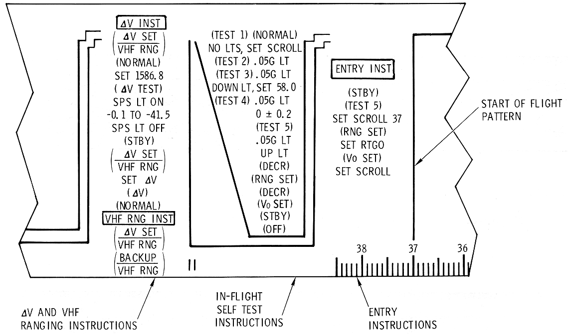
Each entry pattern (EMS Lunar Non-Exit Range Limit
Pattern and
EMS Lunar 3500 NM Range Limit
Pattern) has velocity increments from 37,000 to 4,000 fps
together with entry guidelines. These lines are called G on-set, G off-
set, and range potential guidelines. The G on-set and G off-set lines are
solid lines and tl1e range potential lines are broken.
EMS Lunar Non-Exit
Range Limit Pattern

EMS Lunar 3500 NM
Range Limit Pattern

The G on-set lines slope downward, while the Goff-se t
lines r ay upward and terminate at 24, 000 fps just to the right of the
vertical line at 25, 500 fps (minimum velocity for earth orbit). Below 24,
000 fps the G on-set lines slope downward from the full-lift profile line
which represents the steady-state minimum G entry profile. During entry
the scribe trace should not become parallel to either the nearest G on-set
or G off-set line. If the slope of the entry trace becomes more negative
than the nearest G on-set line, the CM should be oriented such that a
positive lift vector orientation (lift vector up) exists in order to
prevent excessive G buildup. However, if the entry trace slope becomes
more positive than the nearest G off-set line then the CM should be
oriented to produce negative lift (lift vector down) for entry.
The G on-set and G off-set lines are designed to allow
a 2-second crew response time with a single system RCS/SCS 180-degree roll
maneuver should the entry trace become parallel to the tangent of the
nearest guideline.
The range potential lines, shown in hundreds of
nautical miles, indicate the ranging potential of the CM at the pre sent G
level. The crew will compare the range displayed by the range-to-go
counter with the range potential indicated by the entry trace. The slope
and position of the entry trace relative to a desired ranging line
indicates the need for lift vector up or down.
The following functional discussion of the EMS relates
system mechanization to the EMS operation. (See EMS Functional Block Diagram.)
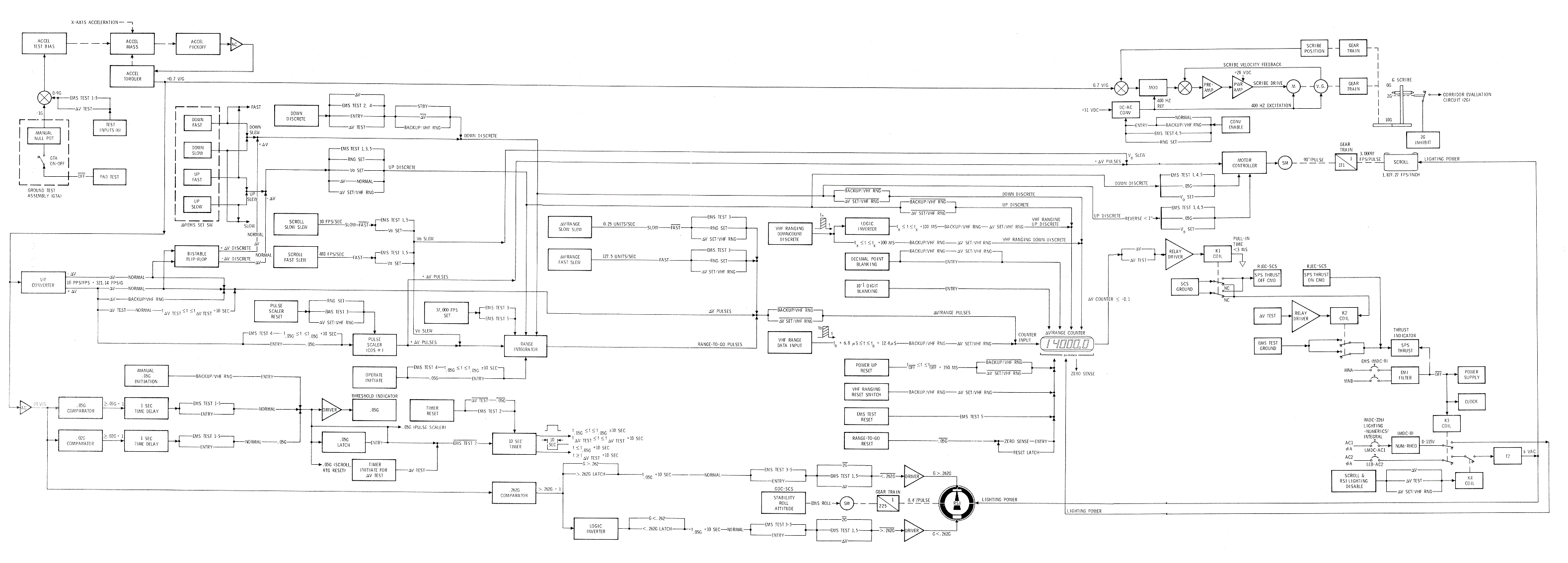
The accelerometer, which is aligned to within ±2
degrees of the SC X-axis, is the only sensor in the EMS. It has three
outputs: low level G to threshold and corridor circuits, high level G to
the flight monitor G axis during entry, and an output to the AID converter
which is used to d rive the delta /RANGE
display and mylar scroll. The difference i n the low and high level G
outputs is scale factor.
Threshold and Corridor Verification Circuits
The threshold and corridor verification circuits use
the accelerometer low level G output. The .05 G comparator will trigger
and illuminate the threshold light (.05 G) if a G level of 0.05G ± 0.005G
is present for 1 ± 0.5 seconds. If the G level drops to 0.02G ± 0.005G,
the light will be extinguished. The corridor evaluation will occur 10.053
± 0.025 seconds after the .05 G threshold lamp is illuminated. The lift
vector up light will illuminate if the G force is greater than
approximately 0.262 ± 0.009G. The lift vector down light will be
illuminated if the G force is less than approximately 0.262 ± 0.009G.
There will be only one corridor verification light turned ON for corridor
evaluation. The corridor lights will be turned off when the flight monitor
G axis drive passes the 2G level.
Scroll Assembly G Axis Drive Circuits
The scroll assembly G axis drive circuits receive the
accelerometer high G level output signal and position the G axis scribe in
vertically. The scribe drive is a normal closed-loop servo circuit with
velocity and position feedback. The loop is biased from zero by the
magnitude of the accelerometer input.
Scroll Assembly Velocity Axis Drive Circuits
The scroll assembly velocity axis drive circuits use
the accelerometer A /D converter output to drive the scroll from right to
left. The A/D converter output is about one pulse for each 0. 1 fps of
velocity change. The motor control circuits and stepper motor cause the
scroll to move from right to left and the present inertial velocity is
read on the scroll. Before entry scroll is initialized to the inertial
velocity by setting the FUNCTION switch to the Vo SET position and using
the delta V/EMS SET switch to slew the scroll to the predicted inertial
velocity value a t 0.05G.
Delta V/RANGE Display Circuits
The delta V / RANGE electronics directly controls the
numeric display value except during VHF ranging operations. The display
will be initialized by a combination of the FUNCTION switch and delta V
/EMS SET switch, except during VHF ranging operations. During AV
operations, the accelerometer A/D converter output pulses are used to
increment or decrement I display value. When the display decreases to a
value of -0.1 fps, a signal is supplied to the SCS for an automatic SCS
control SPS OFF command. For entry, the display will read range to go,
being decremented by the range integrator. The output of the range
integrator will decrease as a function of the inertial velocity stored in
it at any time. The range integrator is decremented to that it contains
the CM present inertial range to-go if properly initialized. The divider
network sends pulses to the flight monitor velocity axis d rive in order
to drive the scroll from right I to left after 0. 05G is sensed. If the 0.
05G function should fail, placing the MODE switch to the BACKUP /VHF RNG
position will initiate the divider network operation to drive the
range-to-go display and the flight monitor scroll from right to left as a
function of G level.
Roll Stability Indicator Drive
The RSI drive function, controlled by the yaw axis of
the GDC in the SGS, requires the correct positive of the two ENTRY
switches (.05G and EMR ROLL) for its correct operation during entry. This
function is described as a normal GDC function in paragraph
GDC Configurations.
Tl1e thrust-off function will provide a logic function
for a SCS thrustoff command any time the delta V /RANGE counter goes to
-0.1 fps. During a delta V mode operation, a relay energizes and provides
a ground to the SCS. This function operates in conjunction with the delta
V and delta V TEST positions of the FUNCTION switch.