
APOLLO
11 OPERATIONS HANDBOOK BLOCK II SPACECRAFT
Telecommunications
System Schematic
Antenna Equipment
Switching Schematic
Personal
Communications Assembly (Comm Carrier)
Personal
Communications Assembly Diagram
Communications Cable
(Electrical Umbilical Assembly)
Intercommunication
System Interfaces
Instrumentation
Equipment Group
Operational
and Flight Qualification Instrumentation
Central Timing
Equipment Diagram
Signal Conditioning
Equipment (SCE)
Signal Conditioning
Equipment Diagram
Pulse-Code
Modulation Telemetry (PCM TLM) Equipment
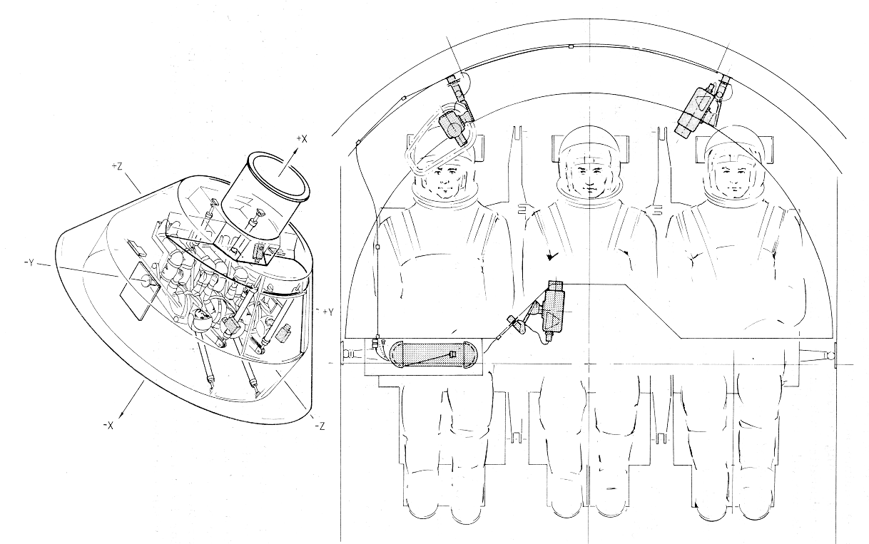
Television Camera
Location Diagram
Color TV and
Monitor Locations Diagram
Color Television
Camera and Monitor Diagram
Data Storage
Equipment Diagram
Tape Transport
Characteristics
Channel Operation
Capabilities Chart
Up- Data Link
Equipment Diagram
RF Electronics
Equipment Group
VHF/ AM
Transmitter-Receiver Equipment
Unified S-Band
Equipment (USBE)
Unified S-Band
Equipment Diagram
S-Band PM
Transmitter Schematic
S-Band FM
Transmitter Schematic
Unified S-Band
Switching Schematic
S-Band Power
Amplifier Equipment
S -Band Power
Amplifier Control and Power Switching Schematic
Premodulation
Processor Equipment
S-Band Operational Spectrums Diagrams
Command Module
Normal S-Band Down Voice
Voice Conference
Between LM or EVA/CSM/MSFN
Command Module
Backup S-Band Down Voice
Recorded CSM
Intercom/LM Voice
MSFN to CSM S-Band
Normal Up-Voice
MSFN to CM S-Band
Backup Up-Voice
CSM INTERCOM/LM
Voice Playback
EVA Biomedical Data
Relay Via S-Band
MSFN to CMS-Band
Backup Up-Voice
PMP Operational
Modes and Output Levels
PMP Data Modulation
Levels Diagrams
Intercom/LM Voice
Output to DSE
VHF Recovery Beacon
Equipment Diagram
Transmit Energy
Characteristics
Received Signal
Characteristics
VHF Recovery
Antenna Equipment
VHF Recovery
Antenna No. 1 Diagram
VHF Recovery
Antenna No. 2 Diagram
Telecommunications
Power Distribution Diagram
OPERATIONAL
LIMITATIONS AND RESTRICTIONS
The communications subsystem is the only link between
the spacecraft and the manned space flight network (MSFN). In this
capacity, the corr1munications subsystem provides the MSFN flight
controllers with data through the pulse code modulated (PCM) telemetry
system for monitoring spacecraft parameters, subsystem status, crew
biomedical data, event occurrence, and scientific data. As a voice link,
the communications subsystem gives the crew the added capability of
comparing and evaluating data with MSFN computations. The communications
subsystem, through its MSFN link, serves as a primary means for the
determination of spacecraft position in space and rate of change in
position. CM-LM rendezvous is facilitated by a ranging transponder and
active ranging system. Through the use of the television camera, crew
observations and public information can be transmitted in real time to
MSFN. A means by which CM and L M telemetry and voice can be stored in the
spacecraft for later playback, to avoid loss because of an interrupted
communications link, is provided by the communications subsystem in the
for1n of the data storage equipment (DSE). Direction finding aids are
provided for postlanding location and rescue by ground personnel.
The following list summarizes the general teleco1nm
functions:
Provide voice communication between
•
Astronauts via the intercom
•
CSM and MSFN via the unified
S-band equipment (USBE) and in orbital and recovery phases via the VHF/ AM
•
CSM and extravehicular astronaut
(EVA) via VHF/AM
•
CSM and LM via VHF/ AM
•
CSM and launch control center
(LCC) via PAD COMM
•
CSM and recovery force swimmers
via swimmers umbilical
•
Astronauts and the voice log via
intercomm to the data storage equipment
Provide data to the MSFN of
•
CSM system status
•
Astronaut biomedical status
•
Astronaut activity via
television,
•
EVA personal life support system
(PLSS) and biomed status
•
LM system status recorded on CSM
data storage equipment
Provide update reception and processing of
•
Digital information for the
command module computer (CMC)
•
Digital time-referencing data for
the control timing equipment (CTE)
•
Real time commands to remotely
perform switching functions in three CM systems
Facilitate ranging between
•
MSFN and CSM via the USBE
transponder
•
LM and CSM via the rendezvous
radar transponder (RRT)
•
CSM and LM via the VHF/ AM
ranging system
Provide recovery aid
•
VHF beacon for location
Provide a time reference for all time-dependent
spacecraft subsystems except the guidance and navigation subsystem.
The functional description of the T/C system is divided
into four parts: intercommunications equipment, data equipment, radio
frequency equipment, and antenna equipment. All of these functional groups
of equipment interface with each other to perform the system tasks. In the
functional descriptions of these parts, such interfaces will be apparent.
The equipment that falls into each group is shown in the
Telecommunications System
Schematic.
Telecommunications
System Schematic

The functions performed by the intercommunications
equipment can be summarized as providing the means for each astronaut to
interface or isolate himself to or from the
•
Intercomm for
astronaut-to-astronaut communications
•
Pad communications for
astronaut-to- launch control center communications
•
VHF/ AM for astronaut-to-MSFN,
EVA, or LM communications
•
USBE for astronaut- to-MSFN
communications
•
Data storage equipment for a
voice log (via intercomm)
•
Swimmers umbilical during
recovery (via intercomm).
The equipment that falls into the intercommunications
grouping 1s listed as follows:
•
Personal communications assembly
•
T-adapter cable
•
Communications cable
•
Audio control panels (MDC-6, -9,
-10)
•
Audio center
•
Swimmers umbilical cable.
The functions of the data equipment can be summarized
as providing
•
Information gathering and
encoding (telemetering) of critical spacecraft and astronaut parameters
•
Conditioning of instrumentation
inputs for compatibility with the telemetry equipment
•
Storage and playback capabilities
of CSM and LM telemetering data, voice log, and scientific parameters
•
Decoding and distributing of
up-data to the proper switching or information receiving systems
•
Frequency and/or time code
signals to other spacecraft equipment
The equipment that falls under the data grouping is as
follows:
•
Central timing equipment (CTE)
•
Signal conditioning equipment
(SCE)
•
Pulse code modulation (PCM)
telemetering equipment
•
Television (TV) camera
•
Data Storage Equipment
•
Up-data link (UDL) equipment
The functions performed by the RF equipment can be
summarized as the transmission and reception of
•
Voice information between
o
CM and MSFN
o
CM and LM
o
CM and EVA
o
CM and recovery forces
•
Telemetering data
o
Between CM and MSFN
o
From LM to CM to MSFN
o
From EVA to CM to MSFN
•
Television from CM to MSFN
•
Ranging and beacon (BCN)
information
o
Pseudo-random noise ranging
signals from MSFN to CM to MSFN
o
Double doppler ranging signals
from MSFN to CM to MSFN
o
X-band radar signals from LM to
CM to LM
o
VHF ranging signals from CM to LM
to CM
o
VHF beacon signals from CM to
recovery forces.
As shown in figure
Telecommunications System
Schematic, the equipment that falls into the rad.io frequency
grouping is
•
VHF/ AM transceivers A & B
•
Digital ranging generator
•
Unified S -band equipment
(primary and secondary xponders and FM xmitter)
•
S-band power amplifiers (primary
and secondary)
•
VHF beacon
•
X-band xponder (rendezvous radar)
•
Premodulation processor
The antenna equipment can be divided into three groups:
VHF antennas and ancillary equipment, S-band antennas and ancillary
equipment, and. beacon antenna. Their overall function is to propagate and
receive RF signals from and to the RF equipment. The ancillary equipment
includes two RF switches, 2 triplexers, and the servo-drive system for the
high-gain antenna (figure 2. 8-2).
Antenna Equipment
Switching Schematic

Personal Communications Assembly (Comm Carrier)
As shown in
Personal Communications Assembly
Diagram the
personal communications assembly (comm carrier) contains redundant
earphones and microphones. The comm carrier can be worn with the space
suit, flight coveralls, or constant wear garment. When used with the space
suit, the comm carrier is interfaced with an integral wiring harness in
the suit. A T-adapter cable is required when the comm carrier is worn with
the flight coveralls or just the constant wear garment to interface to
headset with the comm cable.
Personal
Communications Assembly Diagram

Three lightweight headsets are also available for use
in the CM. They have a single earphone and microphone with a lightweight
head clamp and connecting cable.
T-Adapter Cable
Communications
Cable Diagram
The T-adapter cable is used when the astronaut is
wearing his flight coveralls or just his constant w ear garment to connect
the personal communications assembly and biomed preamplifiers to the comm
cable. An integral cable assembly performs this function when the
astronaut is in his space suit so no T-adapter is necessary. Besides
handling the audio signals to and from the comm carrier, the T - adapter
must handle 16. 8 volts needed by the microphone preamps and biomed
preamps. The output of the biomed preamps is also routed to the comm
cable.

Communications Cable (Electrical Umbilical Assembly)
The comm cable has several functions not the least of
which is providing the path for audio signals to and. from the comm
carrier. It also provides the necessary path for the 16.8 volts required
by the microphone preamps in the comm carrier and the biomed preamps. The
output from the biomed preamps also is carried by the comm cable.
Separate from, but related to, the audio signals from
the comm carrier are the control functions of the comm cable control head.
This control head contains a self-centering rocker switch which, when
depressed on one side or the other, initiates specific functions in the
intercommunications equipment. The I'COM side of the rocker s witch is
depressed when the intercommunications equipment is configured in the
manual (PTT) mode of operation and communications over just the intercom
is desired. The XMIT side of the rocker switch can be used for two
different functions. Normally it is used to enable communications over the
intercom and. RF equipment in any of the three operational modes of the
intercommunications equipment. The XMIT side of the rocker switch can also
be used as a sending key in the S-band key mode of operation.
The Communications
Cable Diagram shows the comm cables interface with the
connectors on the left-hand forward equipment bay (below panel 301) and
the T-adapter cable.
The audio center equipment accomplishes the necessary
aud.io signal amplification and switching to provide the capability of the
following:
•
Intercommunication between the
three astronauts
•
Communication between one or more
astronauts and extravehicular personnel in conjunction with any or all of
three associated radio frequency links, or two external intercom hardlines
•
Recording of audio signals in
conjunction with tape recording equipment
•
Relaying of audio signals.
The audio center equipment consists of three
electrically identical sets of circuitry which provide parallel selection,
isolation, gain control, and. amplification of all voice communications.
Each set of circuitry contains the following components (Audio Center Schematic):
•
Isolation pad, diode switch, and
gain control for each receiver input, and intercom channel.
•
Isolation pad and diode switch
for each transmitter modulation output and intercom channel.
•
An earphone amplifier and a
microphone amplifier.
•
Voice-operated relay (VOX)
circuitry with externally controlled sensitivity.

The equipment operates with three remote control panels
to form three audio stations, each providing an astronaut with independent
control of all common functions. Each station has the capability of
accommodating a second astronaut for emergency operation. Provision is
made in each station to enable voice transmission over any or all
transmitters by means of a voice-operated relay (VOX) circuit or
push-to-talk (PTT) circuit. A "hot mike" is so incorporated as to maintain
continuous intercrew communication using the INTERCOM/PTT mode, and to
require PTT operation for eternal transmission. Enabling a TRANSMIT
function also enables the corresponding RECEIVE function. Sidetone is
provided in all transmit modes.
Audio signals are provided to and from the VHF/ AM
transmitter receiver equipment. USBE (via the PMP), the PAD COMM, and.
intercom bus. The PAD COMM, intercom bus, and all transmitter-receiver
equipments are common to all three stations.
Inputs and outputs are controlled by the VHF/AM,
S-BAND, PAD COMM, and INTERCOM switches on the audio control panels. Each
of these switches has three positions: T/R, OFF, and RCV. Setting any of
the switches to T/R permits transmission and reception of voice signals
over its respective equipment, RCV permits reception only, and OFF
disables the input and the output. The POWER switch of each station, in
either AUDIO/TONE or AUDIO, energizes the earphone amplifier to permit
monitoring. The AUDIO/TONE position also enables the audible crew alarm to
be heard, if triggered, at the respective SC station. Each SC station can
be isolated from the alarm by selecting the AUDIO or OFF position. The
operation of the microphone amplifier in each station is controlled by the
VOX keying circuit or the PTT pushbutton on the comm cable or on the
rotation controller. The VOX circuit is energized by the VOX position of
the MODE switch on each audio control panel. When energized, the VOX
circuit will enable both the intercom and accessed transmitter keying
circuits. The INTERCOM/PTT position permits activation of the PAD COMM,
VHF/AM, and S - band voice transmission circuits by the PTT key while the
intercom is on continuously. The PTT position permits manual activation of
the intercom or intercom and. transmitter keying circuits by depression of
the I'COM or XMIT side of the communication cable switch, respectively.
Six potentiometer controls are provided on each audio
control panel: VOX SENS, PAD COMM, S-BAND, INTERCOM, VHF/AM and MASTER
VOLU1'-1E. The VOX SENS control is used, to adjust the sensitivity of the
VOX circuitry, determining the amplitude of the voice signal necessary to
trigger the VOX keying circuit. The PAD COMM, S-BAND, VHF/ AM, and
INTERCOM volume controls are used to control the signal levels from the
respective units to the input of the earphone amplifier. The MASTER VOLUME
controls the level of the amplified signal going to the earphones.
The intercom bus connects to the recover y interphone
(swimmer umbilical), and the premodulation processor which in turn routes
the signal to the data storage equipment for recording.
An AUDIO SE LECT switch on each audio control panel
allows the astronaut to access himself to the normal audio center circuits
for that station, or through a selection of the BACKUP position, access
himself to the audio control panel and audio center of another station. In
the BACKUP position the commander is accessed to the LM pilot’s panel and
audio c enter, while BACKUP for the CM pilot accesses hi1n to the
commander is panel and audio center. The LM pilot is accessed to the CM
pilot's panel and audio center if he selects the BACKUP mode.
A SUIT POWER switch on each panel controls application
of power to the respective astro11auts personal communications assembly
microphone preamplifiers and the biomed preamplifiers contained in his
constant wear garment.
It is important
to note that most signal processing done by the audio center is of
preparatory nature. In order for any audio signal to be transmitted or
received, the RF equipment must be in the proper operational mode.
The swimmer s umbilical cable is deployed with the dye
marker in the recovery phase of the mission. It provides a hard-line
connection to the spacecraft intercom bus for the recovery force swimmers.
Actual deployment is accomplished by activating the guarded DYE MARKER
switch on MDC-8 which provides 28 vdc to a pyrotechnic actuator.
Intercommunication System Interfaces
The Audio
Interfaces Diagram illustrates the interfaces between the
intercommunications group and the other, telecommunications equipment. One
interface shown that is not readily apparent is the signal path used in
the relay mode of operation. This mode of operation ties the VHF AM and S
-band equipment together to provide a three-way conference capability
between the MSFN, CM and LM, or EVA. The intercommunications equip1nent
enters this process when the received MSFN voice signal (S-band or voice)
is routed to the microphone input of the CM pilot. Then, through proper
switching, this signal is routed to the VHF AM transmitter for relaying to
the LM or EVA. In the relay mode, the CM pilot's microphone is not usable.
The return relay is accomplished by adding the VHF/ AM received voice to
the normal S-Band down voice channel.

Another function not too obvious is voice log recording
and playback. The intercomm bus of the audio center is connected through
the premodulation processor to the data storage equipment (DSE). Any time
the DSE is recording, the conversation on the intercomm bus will be
recorded as well, in some instances, as the received voice from the VHF/
AM equipment. There are no provisions to monitor this recorded voice in
the SC.
Instrumentation Equipment Group
The SC instrumentation equipment consists of various
types of sensors and transducers for providing environ1nental, operational
status, and performance measurements of the SC structure, operational
systerr1s, and experimental equipment. The outputs from these sensors and
transducers are conditioned into signals suitable for utilization by the
SC displays, presentation to the PCM TLM equipment, or both. In addition,
various digital signals are presented to the PCM 1'LM equipment, including
event information, guidance and navigation data, and a time signal from
the CTE.
Many of the signals emanating from the instrumentation
sensors are of forms or levels which are unsuitable for use by the SC
displays or PCM T LM equipment. Signal conditioners are used to convert
these signals to forms and levels which can be utilized. Some signals are
conditioned at or near the sensor by individual conditioners located
throughout the SC. Other signals are fed to the signal conditioning
equipment (SCE), a single electronic package located in the lower
equipment bay. (Refer to Signal Conditioning Equipment
(SCE) section for
signal conditioning equipment.) In addition to conditioning many of the
signals, the SCE also supplies 5-volt d-c excitation power to some
sensors. The SCE can be turned on or off with tl1e POWER-SCE switch on
MDC-3. This is the only control that the crew can exercise over
instrumentation equipment for operational and flight qualification
measurements. These two instrumentation groups are discussed in
Operational and Flight
Qualification Instrumentation
and
Data Equipment Interfaces
sections.
Operational and Flight Qualification Instrumentation
Operational measurements are those which are normally
required for a routine mission and include three categories: in- flight
management of the SC, mission evaluation and system performance, and
preflight checkout of the SC. The operational instrumentation sensors and
transducers are capable of making the following types of measurements:
pressure, temperature, flow, rate, quantity, angular position, current,
voltage, frequency, RF power, and. ''on-off" type events.
Flight qualification measurements may vary between SC,
depending on mission objectives and. state of hardware development. These
measurements will be pulse-code modulated along with the operational
measurements and transmitted to the MSFN.
The Data
Interfaces Diagram illustrates the major interfaces between
the units that make up the data equipment and their interfaces with the RF
equipment group.
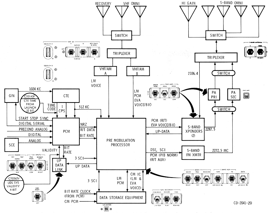
Central Timing Equipment (CTE)
The CTE provides precision square-wave timing pulses of
several frequencies to time-correlate all SC time-sensitive functions. It
also generates and stores the real-time day, hour, minute, and second
mission elapse time (MET), in binary-coded decimal (BCD) format for
transmission to the MSFN. (See the
Central Timing Equipment Diagram
)
Central Timing
Equipment Diagram
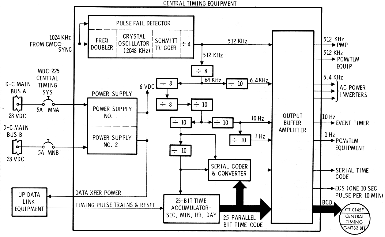
In the primary or normal mode of operation, the command
module computer (CMC) provides a 1024-kc sync pulse to the CTE. This
automatically synchronizes the CTE with the CMC and provides a stability
of ±2 x 10⁻⁶
parts in 14 days. In the event of sync pulse failure, the CTE
automatically switches to the secondary mode of operation with no time
lapse and operates using its own crystal oscillator at a stability reduced
to ±2.2 x 10⁻⁶
parts in 5 days.
The CTE requires approximately 20 watts of 28-vdc power
for its two redundant power supplies. Each one is supplied from a
different power source and through separate circuit breakers. These
circuit breakers, CENTRAL TIMING SYS-MN A and - MN B on MDC-225, provide
the only external means of control for the CTE. The two power supplies
provide paralleled 6-volt d-c outputs, either one of which is sufficient
to power the CTE.
The timing signals generated by the CTE, and their
applications, are listed in the CTE outputs charts.
|
Signal |
Destination |
Purpose |
|
512-kc sq wave |
PCM |
SYNC of internal clock |
|
512-kc sq wave |
PMP |
Modulating signal for S-band emergency key
transmission |
|
6 4-kc sq wave |
EPS inverters (3) |
Sync of 400-cycle a-c power |
|
10-cps sq wave |
Digital event timer |
Pulse digital clock |
|
1-cps sq wave |
PCM |
PCM frame sync |
|
1 pulse per 10 minutes |
ECS |
Discharge water from astronaut suit |
|
25-bit parallel time code output |
PCM |
Time correlation of PCM data |
|
Serial time code output (3) |
Scientific data equipment |
Time correlation of data |
Signal Conditioning Equipment (SCE)
The signal conditioning equipment (SCE) is contained in
a single electronics package located in the LEB. (See the
Signal Conditioning Equipment
Diagram.) Its functions are to convert various kinds of
unconditioned signals from the instrumentation equipment into compatible
0- to 5-volt d-c analog signals, and to provide excitation voltages to
some of the instrumentation sensors and transducers.
Signal Conditioning
Equipment Diagram

The SCE contains the following modules:
•
DC differential amplifier
assembly
•
DC differential bridge amplifier
assemblies
•
AC to DC converter assembly
•
DC active attentuator assembly
•
Power supply +20 vdc, -20 vdc,
+10 vdc, +5 vdc
•
Redundant power supply - +20 vdc,
-20 vdc, +10 vdc, +5 vdc.
The only external control "for the SCE is the
3-position SCE switch on MDC-3. The NORMAL position energizes the primary
power supply and an error detection circuit. If the primary power supply
voltages go out of tolerance, the error detection circuit automatically
switches the SCE to the redundant power supply. The SCE will not
automatically switch back to the primary once it has switched to the
redundant unless power is interrupted.
The AUX position provides for manual switching between
the power supplies. This is accomplished by repeated selection of the AUX
position.
The SCE requires 28-volt d-c power input and consumes
about 35 watts.
The Signal Conditioning Equipment
Diagram shows graphically the input and outputs of the SCE and
its redundant power supply.
Pulse-Code Modulation Telemetry (PCM TLM) Equipment
The function of the PCM TLM equipment (PCM Block Diagram) is to
convert TLM data inputs from various sources into one serial digital
output signal. This single-output signal is routed to the PMP for
transmission to the MSFN or to the DSE for storage. The PCM TLM equipment
is located in the lower equipment bay. Input signals to the PCM TLM
equipment are of three general types: high-level analog, parallel digital,
and serial digital.
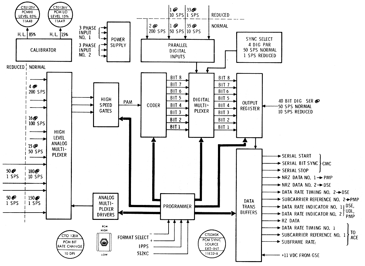
Two modes of operation are possible: the l1igh (normal)
bit-rate mode of 51.2 kilobits per second (kbps) and the low (reduced)
bit-rate mode of 1. 6 (kbps). Operational mode is selected by placing the
TLM INPUTS-PCM switch on MDC - 3 to HIGH or LOW, as applicable. When the
switch is in the LOW position, the high-PCM bit-rate can be commanded by
the MSFN via the UDL equipment. The PCM requires about 21 watts of 3-phase
115/200'-volt 400-cps a - c power. Internal signal flow of the PCM 1s
shown in the PCM
Block Diagram.
The analog multiplexer can handle 365 high-level analog
inputs in the high-bit-rate mode. Four of these signals, 22Al - 4, are
sampled at 200 SPS; 16 signals, 12Al-16, are sampled at 100 SPS; 15
signals, 51Al-15, are sampled at 50 SPS; 180 signal s, llAl-180, are
sampled at 10 SPS; and 150 signals, 10Al - 150, are sampled at lSPS.
These analog signals are gated througl1 the
multiplexer, the highspeed gates, and are then fed to the coder. In the
coder, the 0-to 5 -volt analog signal is converted to an 8-bit binary
digital representation of the sample value. This 8 -bit word is
parallel-transfer red into the digital multiplexer where it is combined
with 38 external 8-bit digital parallel inputs, and 5 internal ones, to
form the majority of the output format.
The external digital parallel inputs fall into three
groups. The first group contains two 8-bit word inputs sampled at 200 S/S
at the high-bit rate only. The second group contains a single 8- bit word
input sampled at 50 S/S at the high bit rate and 10 S/S at the low bit
rate. Th e third, and largest, group contains 35 eight- bit word inputs
sampled at 10 S/S at the high-bit rate and one S/S at the low-bit rate.
The remaining inputs to the digital multiplexer are internal and come from
the coder, sync format, and programmer of the PCM.
This digital parallel information is
parallel-transferred into, the output register where it is combined with
the digital serial input, and then outputted serially into the data
transfer buffer. From here the information is passed on to the
premodulation processor for preparation for transmission over the RF
equipment.
The PCM receives 512-kc and 1-cps timing signals from
the central timing equipment. If this source fails, the PCM programmer
uses an internal timing reference. The timing source being used is
telemetered. Two calibration voltages are also telemetered as a confidence
check of the PCMs overall operation.
The PCM requires about 21 watts of 3-phase 400-cycle
power for its redundant power supplies.
The TV equipment consists of a small, portable TV
camera that can be hand-held, or mounted in the locations shown in the Television
Camera Location Diagram. Its function is to acquire real-time
video information for transmission to the MSFN. The camera is connected to
a 12-foot cable for use throughout the CM. The cable is connected to the
power connector J395 and coax connector J122 on the aft side of the
right-hand forward equipment bay. See the Television Camera Diagram
for physical dimensions.
Television Camera
Location Diagram
The camera is controlled by an ON /OFF switch on the
camera handle and an automatic light control switch on the back. Power is
supplied to the cameras ON/OFF switch through CB13 located on RHEB-225
when the S-BAND AUX TAPE/VOICE B4 switch (MDC-3) is in the OFF position
and the S-BAND AUX TV/SCI switch (MDC-3) is in the TV position. Power
required by the camera is 6.75 watts at 28 volts de.
The composite video signal is sent from the camera to
the premodulation processor where it is then sent to the S-band FM
transmitter and its associated power amplifier for transmission to the
MSFN and to the SM umbilical for hardline communications before lift-off.
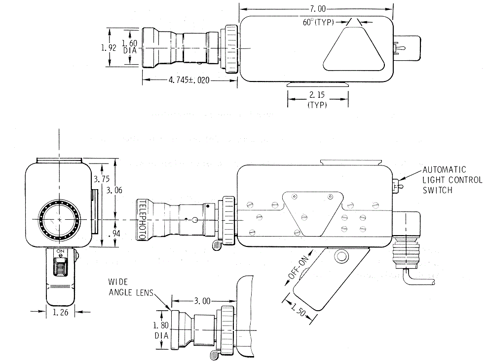
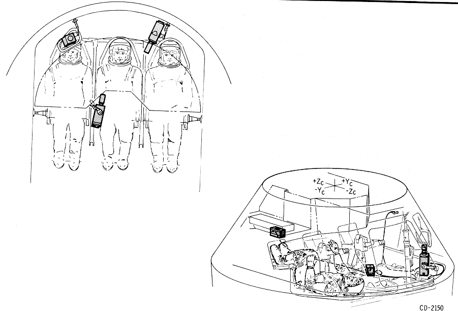
The color TV equipment consists of a small, portable
color TV camera that can be hand-held, or mounted in the locations shown
in the Color
TV and Monitor Locations Diagram. One of the camera functions
is to acquire real-time color video information for transmission to the
MSFN. The camera's primary function is its use during rendezvous and
docking operations. During this period of operation it will be mounted at
the right-hand rendezvous window. A TV monitor is used with the color TV
camera for astronaut viewing of TV operations. See the
Color Television Camera and
Monitor Diagram for
details of camera and monitor. The color TV camera is compatible with the
present black and white TV system in relation to power connections and
switch controls.
Color TV and
Monitor Locations Diagram
Color Television
Camera and Monitor Diagram

Data Storage
Equipment
Data Storage
Equipment Diagram
Data
Storage Equipment Diagram

•
Location: lower equipment bay.
•
Voltage input: 115 -vac 3-phase
400-cp s and/or 28-vdc
•
Power input: 40 watts nominal, 70
watts maximum (3 seconds).
Tape Transport
Characteristics
•
Tape speeds: 3. 75, 15, and 120
ips
•
Operational stability: Stable in
less than 5 seconds
•
Single directional: A rewind mode
is provided.
•
Automatic selection: Tape speed
determined by data rate.
•
Remote control: Complete remote
operation possible via Up Data Link
•
2250 feet of tape giving record
times of 2 hours at 3-3/4 ips and 30 minutes at 15 ips
Fourteen parallel tracks: four CM PCM digital data, and
one of digital clock, one LM PCM data, one CM-LM voice, three scientific
data, and four spare tracks. Spare tracks are available for flight
qualification data.
a.
In put parameters, serial to
parallel conversion of the digital input is performed by the data storage
equipment electronics:
•
Single serial NRZ, 51. 2 kbs data
train, and one 51.2-kc digital timing signal, recorded speed at 15 inches
per second
•
Single serial NRZ, 1. 6 kbs data
train, and one 1.6-kc digital time signal, recorded at 3.75 inches per
second
b.
Output parameters, parallel to
serial conversion of the digital output is performed by the data storage
equipment electronics.
c.
The playback rate of CM PCM is
51.2 kbs for data recorded at 3.75 ips or 15 ips. Playback speeds are 120
ips and 15 ips respectively.
The various operational capabilities and attendant
switching positions are shown in the following list.
Channel Operation
Capabilities Chart

External +28 vdc from the FLT BUS is applied to the
TAPE RECORDER - F ORWARD/REWIND switch. With this switch in the REWIND
position, the tape transport will reverse at 120 ips. The FORWA RD
position of this switch will also run the tape transport in the forward
direction at 120 ips if PLAY or RECORD is not selected. The FORWARD
position of the TAPE RECORDER - F ORWARD/REWIND switch supplies the
excitation to the RECORD/PLAY switch in the FORWARD position. In the
RECORD position, the record and erase circuitry is enabled and power is
applied to the PCM- HIGH/LOW switch. The recording speed in the HIGH
position is 15 ips and in the LOW position the speed is 3.75 ips. In the
PLAY position, the reproduce circuitry is enabled and power is applied to
the PCM/ANLG/ LM PCM switch. The play speed in the PCM/ ANLG position is
internally selected, whereas the play speed in the LM PCM position is only
at 120 ips.
All of the preceding switching functions may be
accomplished by the use of real-time commands from the MSFN through the
up-data (UDL) equipment.
Up-Data Link (UDL)
Equipment 2.8.3.3.9
The function of the UDL equipment is to receive,
verify, and distribute digital updating information sent to the SC by the
MSFN at various times throughout the mission to update or change the
status of operational systems. The UDL (Up- Data Link Equipment Diagram)
consists of detecting and decoding circuitry, a buffer storage unit,
output relay drivers, and a power supply. The UDL provides the means for
MSFN to update the CMC, the CTE, and to select certain vehicle functions.
Up-data information is transmitted to the SC as part of the 2-kmc S-band
signal. When this signal is received by USBE receiver, the 70-kc
subcarrier containing the up-data information is extracted and sent to the
up-data discriminator in the PMP. The resulting composite audio frequency
signal is routed to the sub-bit detector in the UDL which converts it to a
serial digital signal. The digital output from the sub-bit detector is fed
to the remaining UDL circuitry, which checks and stores the digital data,
determines the proper destination of the data, and transfers it to the
appropriate SC system or equipment. The UDL has three controls: two are on
MDC-3 under the UP-TLM bracket and the third on MDC-2. The first, a
two-position switch, is the DATA-VOICE BU switch. In the DATA position,
the 70- kc subcarrier information is routed to the UDL equipment for
normal processing. The VOICE BU position routes the 70-kc subcarrier
information to the UDL equipment and audio centers, thus providing an
alternate path for voice information to be sent in case of failure of the
30-kc subcarrier discriminator.
Up-Data Link
Equipment Diagram
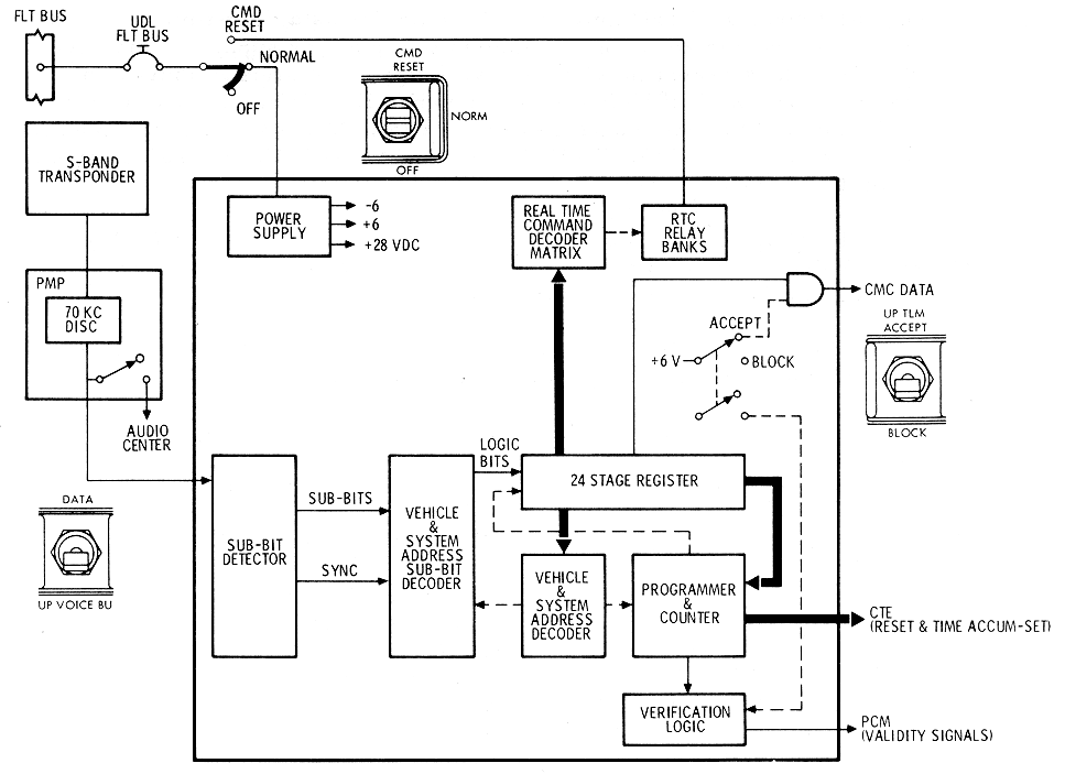
The second switch is the CMD RESET/NORMAL/OFF switch.
The center, NORMAL, position applies power to the UDL and permits nor1nal
operation. The upward position performs a real-time command reset function
and keeps power applied to the power supply. This resets all RTC relays
except those relays affecting the system A abort light and the crew alarm,
so the affected equipment will resume the operational mode dictated by
their control switches on the MDC-3. The OFF position removes the power
from the UDL equipment. The UDL consumes about 12 watts of 28-vdc power.
The third control, on MDC-2 by the DSKY, is labeled
UP-TLM ACCEPT-BLOCK. Th is two-position switch blocks or routes the UDL
message in the command module computer.
The following list gives the real-time commands and
their functions. Some functions require two separate commands.
BLOCK II UDL REAL- T IME COMMANDS
|
Real-Time Commands |
Functions |
|
01 |
Abort Light (System A) On |
|
00 |
Abort Light (System A) Off |
|
07 |
Abort Light (System B) On |
|
06 |
Abort Light (System B) Off |
|
05 |
Crew Alarm On |
|
04 |
Crew Alarm Off |
|
02, 17 |
Spare |
|
03, 12 |
Spare |
|
03, 13 |
Spare |
|
02, 16 |
* Spare |
|
22, 27 |
S-Band Ranging On |
|
23 |
S - Band Ranging Off |
|
22, 26 |
*Astronaut Control (S - Band Ranging) |
|
32, 37 |
S - Band PCM Mode On |
|
33, 37 |
S - Band PCM Mode Off |
|
32, 36 |
* Astronaut Control (S-Band PCM M ode) |
|
42, 47 |
S-Band P.A. High On |
|
43, 46 |
S-Band By-Pass Mode |
|
43, 47 |
S-Band P.A. Low On |
|
42, 46 |
*Astronaut Control (S-Band P.A. Mode) |
|
52, 57 |
Tape Playback PCM/ Analog Mode |
|
53 |
Tape Playback, LEM/PCM Mode |
|
52, 56 |
*Astronaut control (Tape Playback Mode) |
|
62, 67 |
Tape Recorder - Record Mode |
|
63, 66 |
Tape Recorder - Off Mode |
|
63, 67 |
Tape Recorder - Playback Mode |
|
62, 66 |
*Astronaut Control (Tape Recorder
Playback/Record Selection) |
|
72, 77 |
Tape Recorder - Transport Forward |
|
73, 76 |
Tape Recorder - Power Off |
|
73, 77 |
Tape Recorder - Transport Rewind |
|
72, 76 |
*Astronaut Control (Tape Transport) |
|
65 |
PCM Data Rate Low |
|
64, 71 |
PCM Data Rate High |
|
64, 70 |
*Astronaut Control (PCM Data l'.{ate) |
|
41, 45 |
S-Band Tape Mode |
|
41, 44 |
S-Band Tape Off |
|
40, 51 |
S-Band Back-Up Down Voice |
|
40, 50 |
*Astronaut Control (S-Band) |
|
75 |
D OMNI Antenna ON |
|
74 |
Astronaut Control (S - Band Antenna) |
*Resets previously set relays so that
equipment returns to mode shown on control panels.
RF Electronics Equipment Group
The RF electronics equipment group includes all T/C
equipment which functions as RF transmitters or receivers. The antennas
used by this equipment are mentioned only briefly in this paragraph. Refer
to paragraph 2.8.3.5 for more
information on the antennas.
VHF/ AM Transmitter-Receiver Equipment (VHF-AM Block Diagram)
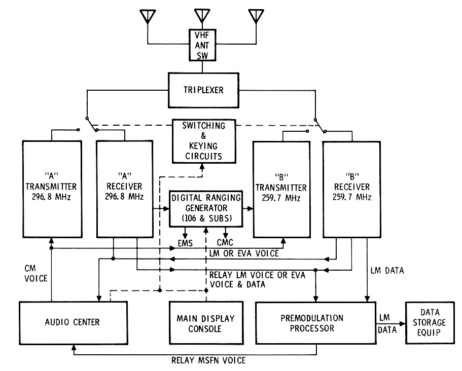
The VHF/AM transmitter-receiver equipment provides the
capability for the following:
•
Two-way voice communications with
MSFN, LM, E VA, and recovery forces.
•
Relay of two- way voice from
either LM or EVA to MSFN (via S-band/MSFN link)
•
Ranging with the LM
•
Reception of PCM data from LM
•
Reception of biomed from EVA.
The equipment is contained in a single enclosure
consisting of 11 subassemblies, 2 coax relays, and 2 bandpass filters
mounted within a three piece hermetically sealed case in the lower
equipment bay.
The equipment group provides two independent VHF/ AM
transmitters and two independent VHF/ AM receivers. One transmitter and
receiver will provide for transmission and reception of voice
communications on a preassigned frequency of 296.8 me. One transmitter and
receiver will provide for transmission of voice communications or
reception of voice communications and data on a preassigned frequency of
259.7 me. Complete isolation of the receiver circuits up to the final
common outputs is provided. A short or open on any output will not degrade
the other outputs.
Various modes of operation are possible in both the
simplex and duplex configurations:
•
Simplex A - Transmit and receive
on 296. 8 me for voice only
•
Simplex B - Transmit and receive
on 259. 7 me for voice only
•
Duplex A - Transmit on 296. 8 me
and receive on 259. 7 me for voice and biomed data
•
Duplex B - Transmit on 259. 7 me
and receive on 296. 8 me for voice and ranging
•
Receive A - Receive on 296. 8 me
only
•
Receive B - Receive LM data on
259. 7 me only
•
Relay - Interfaces with S-band
system for relay to MSFN.
These modes may also be used as a backup VHF recovery
beacon transmitting on 296.8 or 259.7 me.
The VHF/AM transmitter-receiver is controlled by the
VHF-AM controls on panel No. 3 of the main display console (S43, S44, and
S71). The DUPLEX-off-SIMPLEX switches activate the receivers and
transmitters by applying 28-volt d-c power. About 6 watts of power are
required in these modes with the transmitter in standby and about 36 watts
when keyed. In the OFF position, no power will be supplied to the
equipment. The RCV ONLY B DATA/OFF/A switch activates the receivers only.
When the A position is selected, about 2 watts of 28-volt d-c power are
supplied to the 296.8-mc receiver. When the B DATA position is selected,
about 2 watts of 28-volt d-c power are supplied to the 259.7-mc receiver
and the LM data amplifier.
After being selected, the VHF/ AM transmitters can be
enabled either by voice-operated relay (VOX) or by manually depressing the
XMIT switch on the comm cable or rotational controller. The squelch
control varies the level of squelch sensitivity and is located on panel 3
of the main display console.
The transmitters and receivers interface with the main
display console (power control), the audio center (audio inputs, outputs
and PTT functions), and the triplexer (RF inputs and outputs). The
equipment is connected through the triplexer and antenna control switch to
either of the VHF omniantennas in the service module or the VHF recovery
antenna No. 2 in the command module.
Digital Ranging
Generator (VHF Ranging)
2.8.3.4.2
The function of the VHF ranging system is to aid lunar
rendezvous of the CSM with the LM, This is a backup system and. will be
needed only if the LM radar fails, or the LM propulsion system would prove
incapable of effecting rendezvous. This system uses the existing VHF /AM
equipment, and incorporates the use of a digital ranging generator (DRG).
•
Location: Lower Equipment Bay
•
Electrical Power Requirements
o
Voltage input: 28 vdc
o
Power input: 25 watts
•
Mechanical Characteristics
o
Weight: 7.0 pounds
o
Volume: 200 cubic inches
(approximately)
The DRG generates a tone for transmission over the
VHF'/AM 259. 7-mc transmitter, and receives the turn-around range tone
from the LM via the VHF/AM 296.8-mc receiver. A range tracker, in the DRG,
will compute the range by comparing the difference between the transmitted
and received tone, and display this range, real-time, on the entry
monitoring system (EMS). In addition, the range data will also be sent to
the command module computer (CMC), at a rate of once a minute, initiated
by a command from the CMC. This information will be displayed on the DSKY.
Both di splays will be shown in units of 1/100-nautical mile.
This system is activated by turning on the VHF RANGING
switch, on MDC-3. This switch applies +28-vdc power to the DRG, as well as
applying a ground to the keying circuit to key the VHF/AM 259. 7-mc
transmitter, for ranging tone transmission. If the TRACKER alarm light on
the DSKY comes ON, 'this indicates that the data on the DSKY is incorrect.
At the same time the display on the EMS will be reset to read zero. To
restart ranging, the VHF RANGING-RESET-NORMAL switch, on the commander's
audio center panel, is put to RESET, the acquisition phase is started, and
tracking will be established.
Unified S-Band Equipment (USBE)
The USBE (Unified
S-Band Equipment Diagram) consists of two transponders, an FM
transmitter, and power supply contained in a single electronic package in
the lower equipment bay. The USBE will be used for voice communications,
tracking and ranging, transmission of PCM data, and reception of up-data.
The USBE also provides the sole means for transmission of TV.
Unified S-Band
Equipment Diagram

The USBE tracking method employed is the two-way or
double-doppler method. In this technique, a stable carrier of known
frequency is transmitted to the SC where it is received by the
phase-locked receiver, multiplied by a known ratio, and then re-
transmitted to the MSFN for comparison. Because of this capability, the
USBE is also referred to as the S-band transponder.
For determining SC range, the MSFN phase-modulates the
transmitted carrier with a pseudo-random noise (PRN) binary ranging code.
This code is detected by the SC USBE receiver and used to phase-modulate
the carrier transmitted to the MSFN. The MSFN receives the carrier and
measures the amount of time delay between transmission of the code and
reception of the same code, thereby obtaining an accurate measurement of
range. Once established, this range can be continually updated by the
double-doppler measurements discussed earlier. The MSFN can also transmit
up-data commands and voice signals to the SC USBE by means of two
subcarriers: 70 kc for up- data and 30 kc for up-voice.
The USBE transponder is a double-superheterodyne
phase-lock loop receiver that accepts a 2106.4-mc, phase-modulated RF
signal containing the up-data and up-voice subcarriers, and a
pseudo-random noise (PRN) code when ranging is desired. This signal is
supplied to the receiver (S-Band
Receiver Schematic) via the triplexer in the S-band power
amplifier equipment and presented to three separate detectors: the narrow
band loop phase detector, the narrow band coherent amplitude detector, and
the wide band phase detector. In the wide band phase detector, the
9.531-mc IF is detected; and the 70-kc up-data and 30-kc up-voice
subcarriers are extracted, amplified, and routed to the up-data and
up-voice discriminators in the PMP equipment. Also, when operating in a
ranging mode, the PRN ranging signal is detected, filtered, and routed to
the USBE transmitter as a signal input to the phase modulator. In the
loop-phase detector, the 9. 531-mc IF signal is filtered and detected by
comparing it with the loop reference frequency. The resulting d-c output
is used to control the frequency of the 19.0625-mc voltage-controlled
oscillator (VCO). The output of the VCO is used as the reference frequency
for receiver circuits as well as for the transmitter.
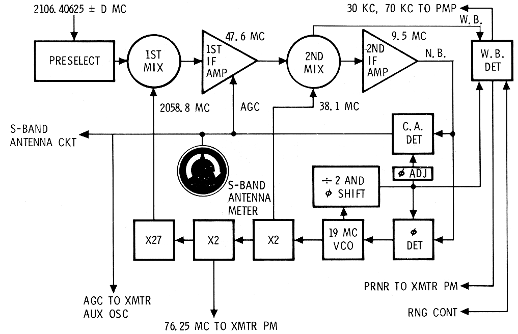
The coherent amplitude detector (CAD) provides the
automatic gain control (AGC) for receiver sensitivity control. In
addition, it detects the amplitude modulation of the carrier introduced by
the high-gain antenna system. This detected output is returned to the
antenna control system to point the high-gain antenna to the earth
station. An additional function of the CAD is to select the auxiliary
oscillator to provide a stable carrier for the transmitter, whenever the
receiver loses lock. The AGC circuitry also supplies a signal to the
S-BAND ANTS-meter located on the lower right on MDC-2. A received relative
signal strength is indicated by this meter.
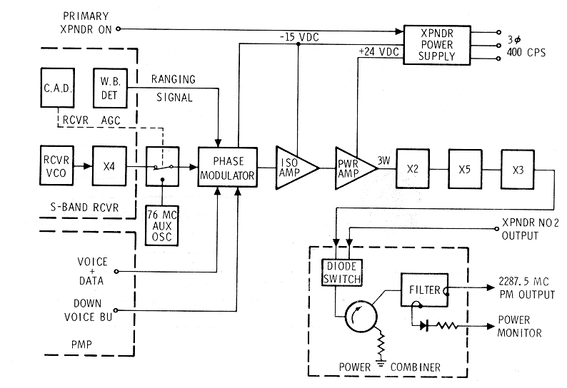
The USBE transponders are capable of transmitting a
2287.5-mc phase-modulated signal. The initial transmitter frequency is
obtained from one of two sources: the VCO in the phase-locked USBE
receiver or the auxiliary oscillator in the transmitter. Selection of the
excitation is controlled by the CAD. If ranging has been selected, the
up-link information is routed from the receiver wide band detector to the
phase modulator in the transponder transmitter (S-Band PM Transmitter Schematic).
The phase modulator also can receive premodulated CSM voice and PCM data
from the PMP in a normal mode or backup voice in event of a malfunction.
The phase modulator signal is amplified to 3 watts by a power amplifier
and sent into a X30 variactor multiplier, where much of this power is
dissipated. The final power output through the power combiner is about 250
mw. About 20 watts of 3-phase 400-cycle a-c power and 2 watts of 28-vdc
power are required by each transponder.
S-Band PM
Transmitter Schematic
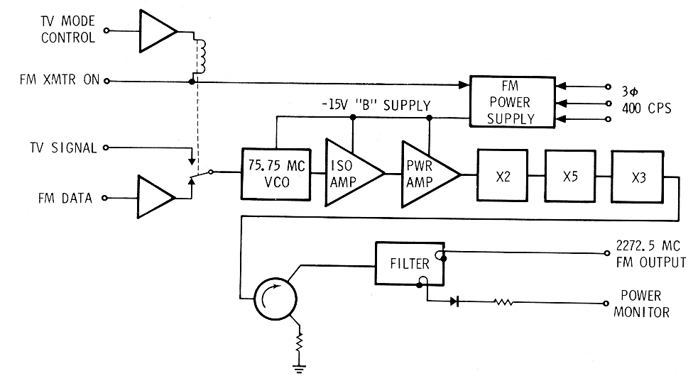
The USBE also contains a separate FM transmitter which
operates at 2272.5 mc (S-Band
FM Transmitter Schematic). This separate S-band transmitter
permits time-shared scientific, television, or playback data to be sent to
the MSFN while voice, real-time data, and ranging are being sent
simultaneously via the transponder. The transmitter VCO receives
modulation from the FM mixer or TV output of the PMP. The frequency
modulator signal passes through two stages of amplification and then is
sent through three multipliers, X2, X3, and X5 respectively. A ferrite
circulator is used on the output of the final multiplier to preclude
reflected power from feeding back and degrading the signal. The output
power is approximately 100 mw. The USBE FM transmitter requires about 8
watts of 3-phase 400-cycle a-c power and 1 watt of 28-vd.c power.
S-Band FM
Transmitter Schematic
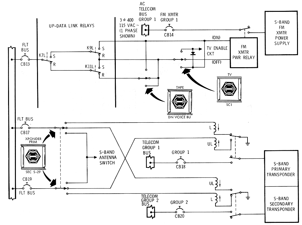
Operational configurations of the USBE are controlled
by the S-band switches on MDC-3. Individual functions are described in the
Controls and Displays, section 3, while control circuits involved with the
USBE are shown in the Unified
S-Band Switching Schematic.
Unified S-Band
Switching Schematic
S-Band Power Amplifier Equipment
The S-band power amplifier (PA) equipment (S -Band Power Amplifier Control
and Power Switching Schematic) is used to amplify the RF
output from the USBE transmitters when additional signal strength is
required for adequate reception of the S-band signal by MSFN. The
amplifier equipment consists of a triplexer, two traveling-wave tubes for
amplification, power supplies, and the necessary switching relays and
control circuitry. The S-band PA is contained in single electronics
package located in the lower equipment bay. Each power amplifier requires
about 15 watts of warm-up, 45 watts at low-power and 90 watts at
high-power of 3-phase 400-cycle a-c power and about 2. 5 watts of 28-vdc
power.
S-Band Power
Amplifier Control and Power Switching Schematic
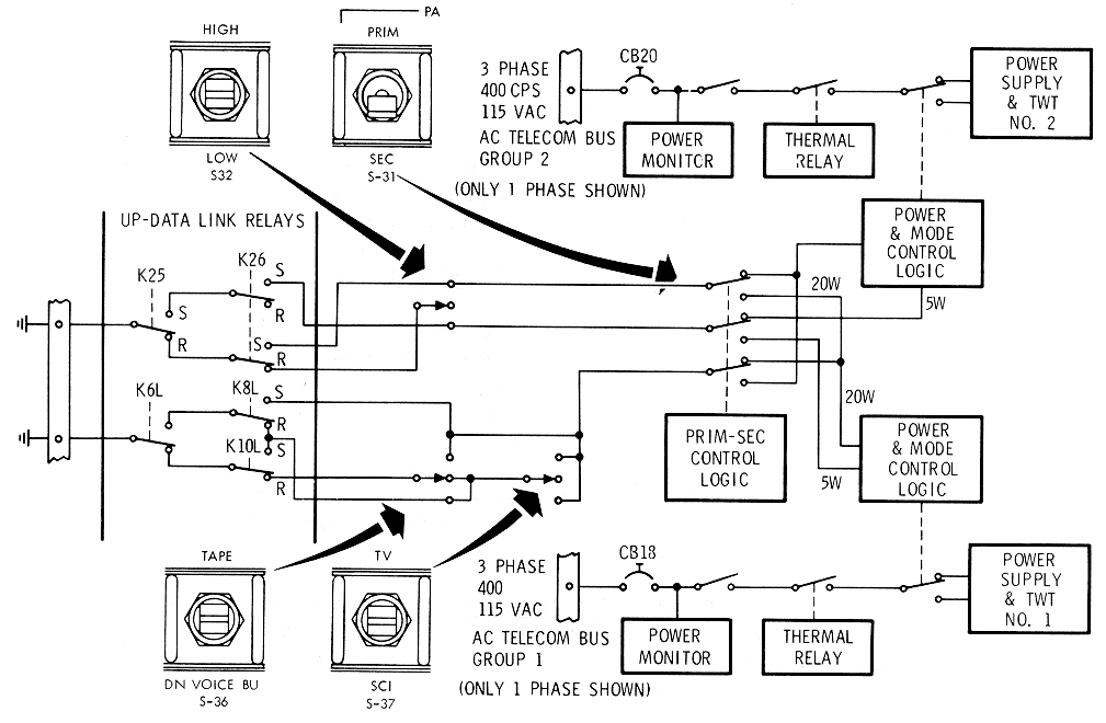
All received and transmitted S-band signals pass
through the S-band PA triplexer. The 2106.4-mc S-band carrier, received by
the SC, enters the S-band PA triplexer from the S-band antenna equipment.
The triplexer passes the signal straight through to the USBE receiver. The
2287.5-mc output signal from the USBE transponder enters the S-band PA
where it is either bypassed directly to the triplexer and. out to the
S-band antenna equipment, or amplified first and then fed to the
triplexer. There are two power amplifier modes of operation: low power and
high power. The high-power mode is automatically chosen for the power
amplifier connected to the F M transmitter.
Power for the power a1nplifier comes from the telecomm
group circuit breakers 1 and 2. Separate 3-phase 115-volt 400-cps power
sources are employed to drive each traveling wave tube and its attendant
power supply. The S
-Band Power Amplifier Control and Power Switching Schematic shows the controlling
circuits involved with power distribution to the power amplifier.
Premodulation Processor Equipment
The premodulation processor (PMP) equipment provides
the interface connection between the airborne data-gathering equipment and
the RF electronics. The PMP accomplishes signal modulation and
demodulation, signal mixing, and the proper switching of signals so that
the correct intelligence corresponding to a given mode of operation is
transmitted.
These modes, which are listed in this section, are
shown on the· S-band operational spectrum (S-Band Operational Spectrums
Diagrams). The PMP uses a maximum power of 12. 5-watt at
28-volt d-c.
S-Band Operational
Spectrums Diagrams
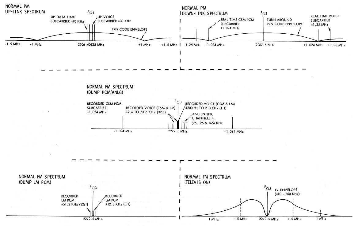
Command Module
Normal S-Band Down Voice
The input voice signal from the audio center equipment
is pre-emphasized, clipped, and frequency modulates the 1250-kc voice VCO.
The voice subcarrier may be frequency- multiplexed with the PCM/PM 1024-kc
subcarrier for PM transmission via the USBE (unified S -band equipment).
Voice Conference
Between LM or EVA/CSM/MSFN
The received VHF/AM LM or EVA voice is amplified and
linearly mixed (time-shared) with the real-time CSM voice for frequency
modulating the 1250- kc voice VCO. The received S-band up-voice 30-kc
subcarrier is demodulated and parallel outputs are provided for input to
the aud.io center equipment and for the navigator 1s mike input to the
navigator1s audio c enter. With the navigator's audio control panel
positioned for VHF/ AM VOX transmission to EVA or LM, the relay of MSFN
voice may be accomplished. The above provisions give a conference
capability between LM or EVA, CSM, and MSFN.
Command Module
Backup S-Band Down Voice
The input voice signal from the audio center equipment
is pre-emphasized and. clipped. The voice signal is then routed directly
to the USBE, bypassing the voice modulator, for base band phase-modulation
(PM) on the S-band carrier transmission to MSFN.
Recorded CSM
Intercom/LM Voice
An AGC circuit is provided to process LM voice which is
linearly mixed with the input voice signal from the CSM intercom bus. An
isolation amplifier is used at the CSM INTERCOM/LM voice output for
recording in the DSE (data storage equipment).
MSFN to CSM S-Band
Normal Up-Voice
The MSFN up-voice is PM/FM voice via S-band. The
received, frequency-modulated 30-kc subcarrier from the USBE is bandpass-
filtered and demodulated in the PMP. The output voice signal is low-pass
filtered and routed to the aud.io center equipment input.
MSFN to CM S-Band
Backup Up-Voice
The MSFN backup up-voice is PM/FM voice via S-band·.
The MSFN voice is switched from the 30-kc subcarrier to the 70-kc
subcarrier and linearly mixed with the up-data. This bypasses the up-voice
detector in the PMP.
CSM INTERCOM/ LM
Voice Playback
The playback-to-record ratio may be either 32:1 or 1:1
dependent upon the CSM PCM recorded bit rate. The input signal from the
DSE is limited, filtered, and frequency-multiplexed with the three
scientific subcarriers and stored PCM data on the 1024-kc subcarrier for
FM transmission via the USBE.
The CSM television camera input signal is a direct
de-coupled output signal to the USBE for FM base band transmission. An
additional isolation amplifier attenuator circuit is provided for
ac-coupled output to the spacecraft umbilical.
The
CSM PCM data input signal biphase modulates the 1024-kc subcarrier. The
subcarrier is filtered and frequency-multiplexed with the voice 1250-kc
subcarrier. The output signal phase-modulates (PM) the carrier for
transmission via the USBE.
EVA Biomedical Data
Relay Via S-Band
The relay of EVA biomed will be accomplished
simultaneously with CSM or EVA voice in the same manner as described in
the voice conference mode.
The up-data signal is processed the same as up-voice
except the subcarrier c enter frequency is 70 kc and the output is routed
to the up- data link decoder.
Three real-time scientific analog telemetry inputs
frequency-modulate three subcarrier oscillators. The three rea l-time
subcarrier signals are mixed and the composite signal frequency modulates
the S-band carrier for FM transmission via the USBE.
The CSM stored PCM TLM data biphase modulates the
auxiliary 1024 -kc sine wave subcarrier. This subcarrier is
frequency-multiplexed with the playback of scientific data and LM/INTERCOM
voice for modulation of the S-band FM modulator and transmission to MSFN.
The LM stored data is played back at 32:1, linearly
attenuated and directly modulated base band on the S-band FM carrier .
The stored scientific analog data frequency-modulates
three subcarrier oscillators (SCO). The SCOs are frequency-multiplexed
with the stored PCM/ T LM 1024 -kc subcarrier and the LM/ INTERCOM voice
playback signal. The composite signal frequency modulates the S-band
equipment.
To provide a keyed output for emergency key
communications, the 512-kc CTE clock input may be keyed by depressing the
XMIT side of the rocker switch located on the astronaut's comm cable. The
key closure controls a gated amplifier from which the keyed signal is
routed to the USBE. A 400-cps sidetone is also keyed by the PTT. This
signal is mixed into the PMP up-voice output circuitry and routed through
the audio center to the earphones. The S-BAND-T/R switch on the audio
control panel is set to T/R or REC.
The CM voice input is pre-emphasized, clipped, and
routed directly to the S-band for PM transmission, bypassing the PMP voice
modulator.
CM Auxiliary PCM
Telemetry Subcarrier Modulator
The real-time PCM T LM input may be switched by S54
(AUX position) to the auxiliary bi phase modulator with the output being
switched to the PMP PM MIXER output for S-band PM transmission and to the
FM mixer output for S-band FM transmission.
MSFN to CMS-Band
Backup Up-Voice
The MSFN voice is placed on the 70-kc up-data
subcarrier. This enables the use of the 70-kc subcarrier for time-shared
voice and data.
The PMP has redundant switchable regulators to provide
power to all PMP circuitry. When switch S54 is in the AUX position, the
auxiliary +18-volt d-c regulator is in use. Also the auxiliary 1. 024-mc
biphase modulator which normally handles stored CM PCM data is switched to
handle real-time CM PCM data.
PMP Operational
Modes and Output Levels
Output signals are provided in combinations and levels
as described in the following. Control panel switches, used to achieve the
various modes are illustrated in the block diagram (PMP Data Modulation Levels
Diagrams).
PMP Data Modulation
Levels Diagrams
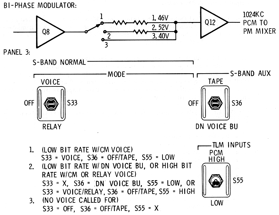
When S54 switch is in the NORMAL position, power is
supplied to all PMP circuitry from the normal +18-volt regulator. When
switch S54 is in AUX position, auxiliary +18-volt regulator is used. Also
the auxiliary 1.024-mc biphase modulator which normally handles stored
CM/PCM data is switched to handle real-time CM/PCM data.
The three R/T scientific analog data signals are
supplied to the DSE through the PMP except when switch S37 is in the SCI
position.
When S37 is in the SCI position, the three R/T
scientific analog data signals are applied directly to the FM mixer in the
PMP for transmission via the S-band FM transmitter.
Intercom/LM Voice
Output to DSE
The intercom and LM voice output i s supplied for DSE
recording at all times power is applied to the PMP.
When switch S38 is in the DATA position, the up-voice
signal from the 30-kc demodulator is supplied as an output to the audio
center. The 70-kc demodulator supplies an up-data output to the up-data
link decoder.
When switch S38 is placed in the BU VOICE position, the
70-kc demodulator output is switched to the up-voice output terminals, as
an output to the audio center
The television signal input is provided as a direct
output. Coaxial terminals having 100-ohm ±5 percent impedance are used.
This channel will pass frequencies from dc to 500 kc with no more than
0.5-db attenuation.
A TV umbilical output is also provided through an
isolation amplifier. Output voltage is no greater than the TV input signal
and is no less than one volt peak-to-peak, for a 1.9-volt peak-to-peak
input signal at 1000 cps. Frequency response in the band from 10 cps to
500 kc is no more than 3 db below the peak response. This output is
protected against open or short circuit conditions.
Signals supplied to the FM terminals for trans1nission
on USBE are:
•
Real-time scientific data
•
Stored CM LM voice
•
Stored LM PCM
•
Stored scientific data
•
Stored CM PCM data
•
Television
•
Auxiliary real-time CM PCM data.
These signals are selected by appropriate combinations
of switches S36, S37, and S49.
Subcarriers are selected by suitable configurations of
switches. Subcarriers selected for phase modulation of the USBE are:
•
1. 024-mc biphase modulated by
real-time CM PCM data
•
1. 25-mc VCO frequency modulated
by:
o
CM voice, or
o
CM voice and. LM/ EVA voice and
biomedical data
•
512-kc emergency key signal.
These signals are selected by appropriate combinations
of switches S33, S34, S 36, and S44. Switch positions and. the output
level of each subcarrier are shown on the
PMP Data Modulation Levels
Diagrams.
The overall functions of the PMP are summarized in the
PMP
Block Diagram .

The VHF recovery beacon equipment (VHF Recovery Beacon Equipment
Diagram) provides line-of-sight direction-finding capabilities
to aid in locating the SC during the recovery phase of the mission. The
3-watt beacon signal emitted is an interrupted 243-mc carrier, modulated
by a 1000- cps square wave. The signal is transmitted for 2 seconds, then
interrupted for 3 seconds.
VHF Recovery Beacon
Equipment Diagram
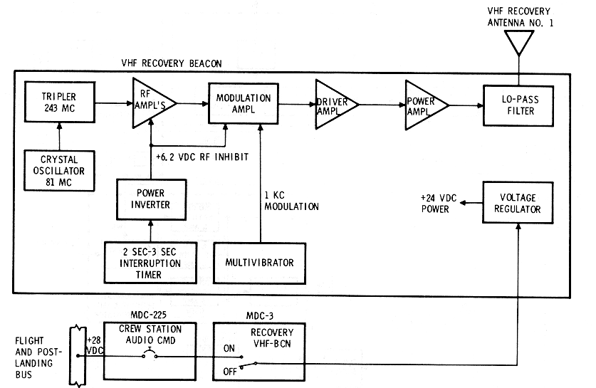
Manual control of the equipment is provided by the
RECOVERY VHF-BCN, two-position ON/OFF switch on MDC -3. The beacon
requires a maximum of 10-watt of 28-vdc power.
The output of the VHF recover y beacon equipment is fed
to VHF recovery antenna No. 1, which i s deployed automatically when the
main chutes are deployed.
The transponder (RRT
Block Diagram) is located in the command and service module
(CSM) and. performs the function of receiving the LM rendezvous radar (RR)
X-band CW signal, and retransmitting (back to the LM) a phase-coherent
signal.
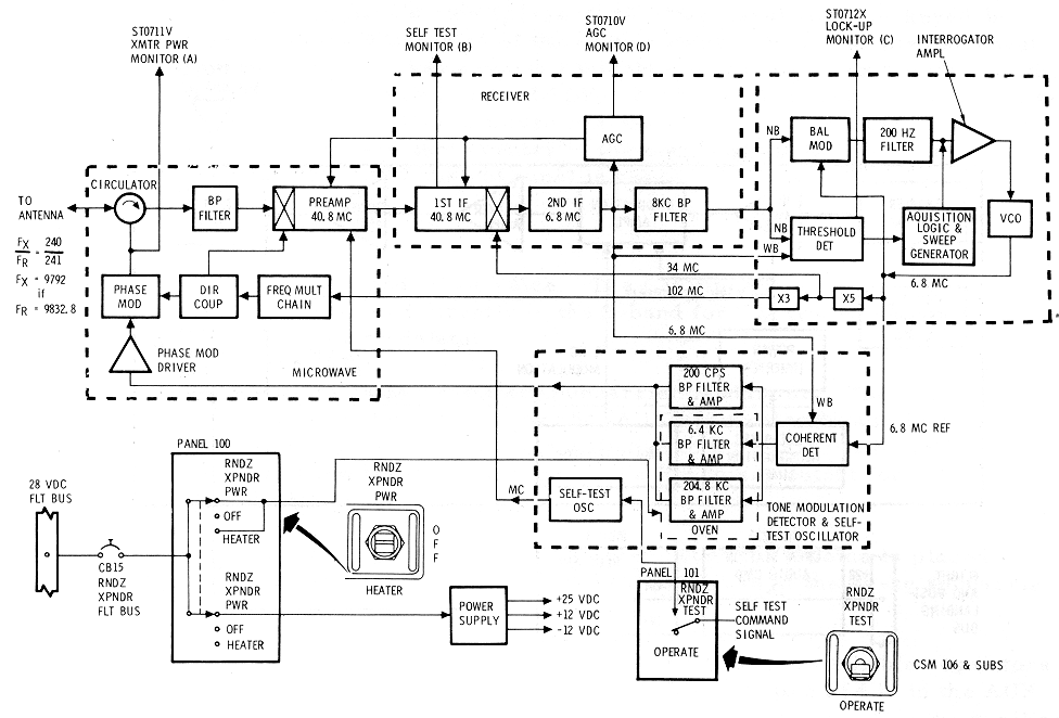
The 240-milliwatt return signal is offset in
fundamental carrier frequency from the received signals and contains the
same modulation components phase-related with respect to the received
signal.
The transponder is a part of the LM radar subsystem
which consists of a rendezvous radar in the LM, the transponder in the
CSM, and a landing radar mounted in the descent stage of the LM. The
landing radar and the descent stage are left on the lunar surface when the
lunar exploration is completed.
During the descent to the lunar surface, the LM and CSM
maintain continuous radar contact through the rendezvous radar-transponder
link. During the latter part of the descent phase, the landing radar
measures the altitude and velocity of the LM with respect to the lunar
surface.
At the end of the lunar stay, the rendezvous radar in
the LM is used to track the transponder in the orbiting CSM to obtain
orbital parameters, which are used to calculate the launching of the LM
into a rendezvous trajectory.
In the rendezvous phase, the LM and CSM again maintain
radar contact to obtain information needed for midcourse correction,
rendezvous, and docking operations. By accepting the weak rendezvous radar
transmitted signal, as discussed in preceding paragraphs, and by
retransmitting (back to the LM) the phase-coherent return signal, the
range capabilities are greatly increased.
Operates with the rendezvous radar (RR) in a closed
loop tracking system at LOS range between 50 feet and 400 NM.
The transponder will retransmit each of the range tones
received from the rendezvous radar at the following maximum phase shifts:
|
Tone Frequency |
Max. Deg. Phase Shift |
|
200 cps |
±0.69° |
|
6.4 kcs |
±1.0° |
|
204.8 kcs |
±3° |
1 /4 percent or 1 foot per second (whichever is
greater) based on an LGC sampling period of 100 milliseconds.
Angular coverage over a solid angle of 160 ° by 105 °.
Acquires the rendezvous radar with a detection
probability of 98 percent in a period of 1.3 seconds with a signal ·'equal
to or greater than -123 dbm at the transponder antenna.
The transponder will be in the signal search mode at
all times that the transponder is in an ON condition and no signal is
being received from the rendezvous radar.
The transponder will be in its transponder mode at all
times that a signal is being received from the rendezvous radar. Signals
equal to or greater than -123 dbm which fall within the transponder
frequency range are automatically detected and acquired by the
transponder.
The transponder will be in the self-test mode when the
self-test enable signal is applied to the transponder assembly.
The transponder will be in standby mode when the heater
position is selected for the 24 minutes it takes to warm the filters to
160°±1°F.
Gain is maintained over a solid angle of 160° x 105°.
Linear with cross-polarized components 20 db down from
the main component.
Transmit Energy
Characteristics
Greater than 240 milliwatts.
Signal search, 9792.0 mc ±25 kcs and. swept ±104 kc
minimum.
Transponder mode equal to the received frequency times
240/241.
Received Signal
Characteristics
9832. 8 mc ±30 kc offset by a doppler frequency within
the range of ±49 kc with maximum rate of change of 500 cps2.
At antenna terminals, -123 dbm to -18 dbm.
Provides 40.8 mc for receiver testing and is coupled
into the receiver preamplifier.
From control/display +12 vdc ±10 percent and current of
20 ma ±10 percent.
From transponder to the control/ display assembly
self-test switch +25 volts ±10 percent.
From transponder to the control/ display monitor meter,
panel 101.
Monitor outputs to the control/display panel:
|
AGC monitor |
0 to 4.5 volts |
|
Frequency lockup search |
0±0.4 volts dc |
|
Transponder mode |
4.5 volts dc ±10 percent |
2.5±0. 4 volts de for specified minimum power (5 volts
dc maximum).
|
Operating voltage |
Normal 25 to 31.5 volts |
|
Emergency periods not
exceeding 5 seconds |
+20 to +25 volts dc +31.5 to
+32 volts dc |
|
Transients limits not
exceeding 5 minutes |
+50 volts for 10 usec at 10
pps repetition rate. |
|
|
-100 volts for 10 usec at 10
pps repetition rate. |
|
Maximum input power excluding
heater |
60 watts at +28 vdc |
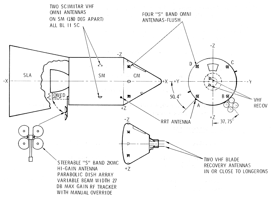
The antenna equipment group contains all the SC
antennas and ancillary equipment used in the T/C system. For the antenna
locations, see the Antenna
Locations Diagram.
The VHF omniantennas and ancillary equipment consist of
two VHF scimitar antennas, a VHF triplexer, a VHF antenna switch, and the
necessary signal and control circuits. The function of this equipment is
to provide capabilities for radiation and pickup of RF signals in the VHF
spectru1n. The VHF/AM transceivers, which work through this equipment,
operate at 296.8 mc and 259.7 mc. Provisions are also made for the
checkout of the PLSS com1nunicati on equipment through this equipment.
The VHF triplexer is a passive, three-channel filtering
device which enables three items of VHF transmitting and receiving
equipment to utilize one VHF antenna simultaneously. The three-channel
filters are composed of two tuned cavities each, which function as
bandpass filters. No power is required by the device and there are no
external controls.
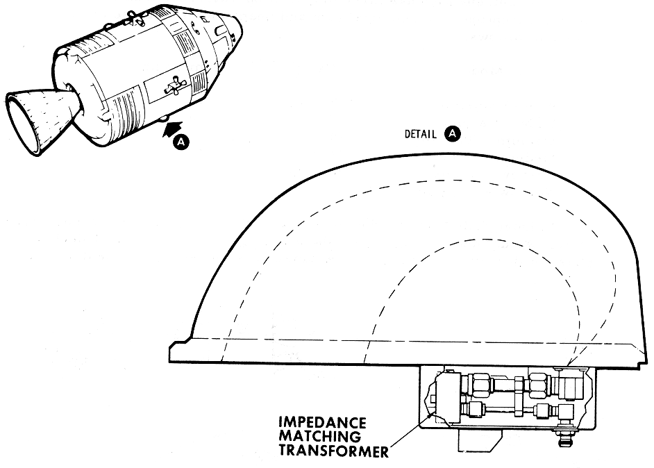
The VHF scimitar antennas, shown in the Scimitar Antenna Diagram,
are omni-antennas with approximately he1nispherical radiation patterns.
Because of its characteristic shape, this type of VHF antenna is called a
scimitar.
These two VHF antennas are located on opposite sides of
the service module. One is located near the + Y axis and is called the
right VHF antenna; the other is located near the -Y axis and is called the
left VHF antenna. Because of their approximate hemispherical radiation
patterns, full omnidirectional capabilities can be obtained only by
switching from one antenna to the other. This is accomplished with the VHF
ANTENNA remote control switch on MDC-3 for VHF communications.
The high-gain antenna is provided for use with the
unified S-band equipment to provide sufficient gain for two-way
communications at lunar distances. To accomplish this, the antenna can be
oriented manually or automatically toward the MSFN stations for maximum
operational efficiency.
The antenna also has three modes of operation for
transmission and two for reception. The nominal gain and beam widths of
these modes are listed as follows:
|
Mode |
Gain |
Beam Width |
|
Wide-Transmit |
9.2 db |
40° |
|
Wide-Receive |
3.8 db |
40° |
|
Medium-Transmit |
20. db |
11.3 ° |
|
Medium-Receive |
22.8 db |
4.5 ° |
|
Narrow-Transmit |
26.7 db |
3.9 ° |
|
Narrow-Receive |
23.3 db |
4.5° |
The High
Gain Antenna Diagram shows the antenna in both the deployed
and nondeployed state. Actual deployment takes place during transposition
and. docking phase of the mission when the SLA panels are opened. After
deployment, the positioning circuitry is enabled. Manual controls,
position readouts, and. a signal strength meter are provided on MDC-2 to
allow normal positioning of the antenna for initial signal acquisition.
After acquisition, the antenna is capable of automatically tracking the RF
signal within the travel limits of its gimbaling system. The propagation
and reception mode is selectable on the same panel.
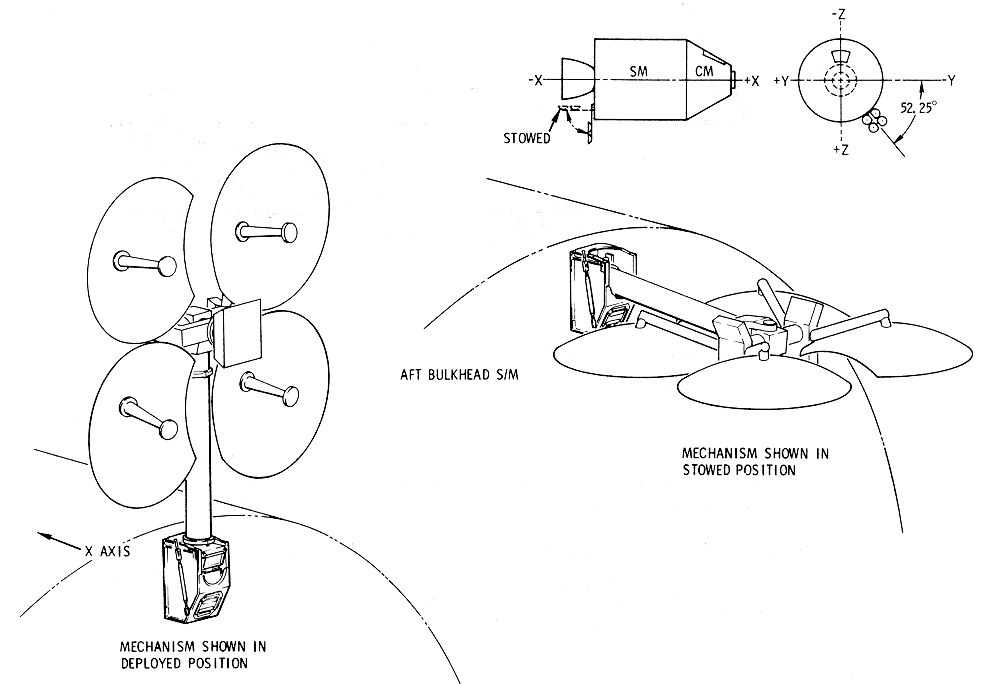
The antenna itself is made up of a four-parabolic dish
array whose attendant feed horns are offset 10 degrees for the desired
propagation pattern and a cluster of four feed horns enclosed in the
center enclosure. In the wide mode, the center feed horns are used for
transmission and reception of signals. In the medium mode, one of the
parabolic dish-reflector antennas is used for transmission and all four of
the dish antennas are used for reception of S-band signals. The narrow
mode employs the four parabolic dish antennas for transmission and
reception of S-band signals.
The function of the four S-band omniantennas is to
transmit and receive all S-band signals during the near-earth operational
phase, with a backup capability to support the high-gain S-band antenna in
the lunar sequence. Locations are shown in the
Antenna Locations Diagram
at Xc=20.766 and 45 degrees off the +Z, - Y, -Z and +Y axis.
The antennas are flush-mounted, right-hand polarized
helical, and in a loaded cavity. They are rated at 15 watts cw at 2100 to
2300 mc.
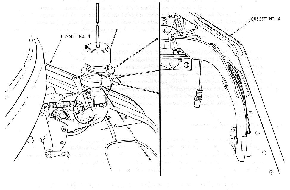
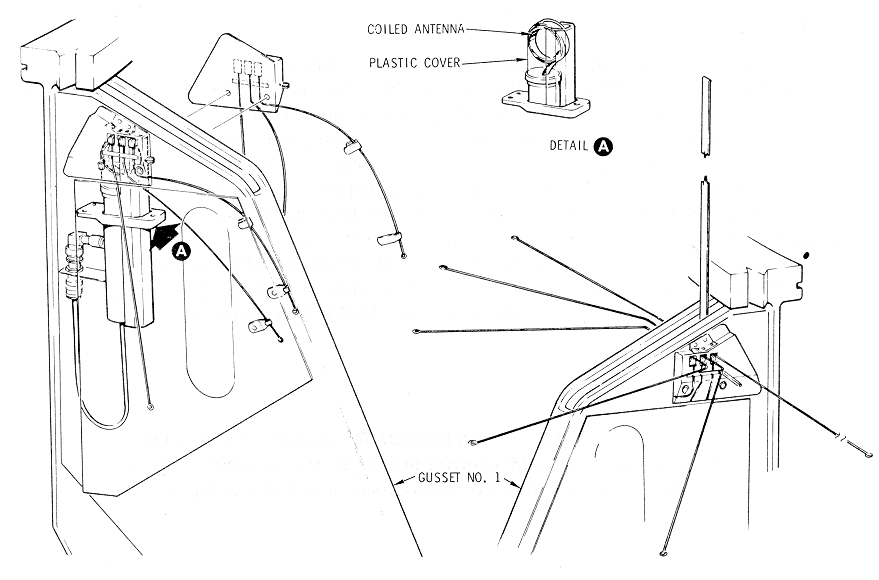
VHF Recovery Antenna Equipment
There are two VHF recovery antennas, No. 1 and No. 2,
stowed in the forward compartment of the SC. Each antenna consists of a
quarter-wave stub, 11 inches long, and. a ground plane. They are
automatically deployed 8 seconds after main parachute deployment, during
the descent phase of the mission. (See the
VHF Recovery Antenna No. 1
Diagram and the VHF
Recovery Antenna No. 2 Diagram.)
VHF Recovery
Antenna No. 1 Diagram
VHF Recovery
Antenna No. 2 Diagram
VHF recovery antenna No. 1 is connected to the VHF
recovery beacon equipment. VHF recovery antenna No. 2 is to be used with
the VHF/AM transmitter-receiver equipment and is connected to the VHF
antenna switch with a coaxial cable. An access hatch is provided to allow
either of the VHF recovery antennas to be used with the GFE survival
transceiver. This requires that the coaxial cable from one of the antennas
be manually disconnected at the triplexer and reconnected to the survival
transceiver.
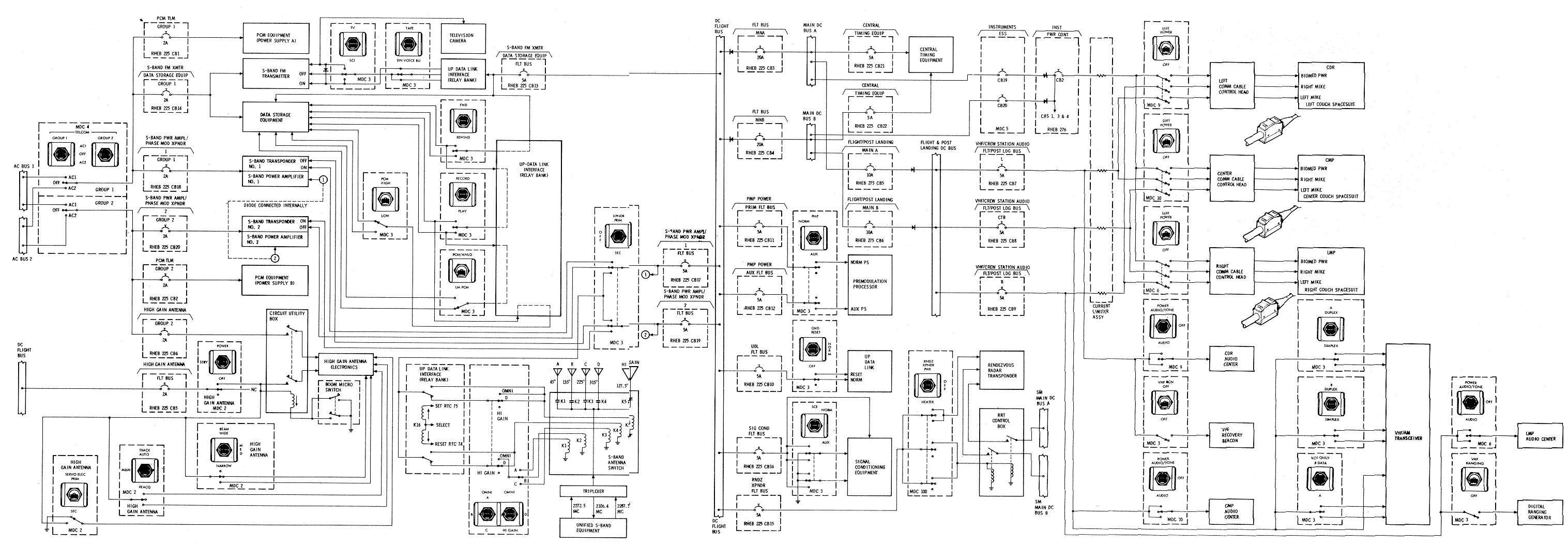
Electrical power distribution for the
intercommunication, data, instrumentation, RF and antenna equipment is
summarized on the Telecommunications Power
Distribution Diagram. In most cases, the power circuit for
each piece of equipment was covered in the respective functional
description. The majority of the circuit breakers for the
telecommunication system are located on MDC-225.
Telecommunications
Power Distribution Diagram
OPERATIONAL LIMITATIONS AND RESTRICTIONS
a.
Simultaneous selection of DUPLEX
A and B gives the same operation as selection of SIMPLEX A and. B.
b.
Only LM PCM telemetering data can
be received only on RCV B DATA.
a.
When UP TLM/VOICE BU is chosen,
the output of the data discriminator is sent to both the audio center and
the up-data link equip1nent.
b.
Low-bit rate P CM data can be
transmitted with down VOICE BU. If only VOICE transmission is desired, the
PCM switch must be at OFF and the TLM INPUT PCM switch must be at HIGH for
the best circuit margins.
c.
Selection of the AUX PMP power
supply precludes tl1e trans1nission of recorded data from the data storage
equipment. Real-time PCM is available for transmission over both the
S-band transponder and FM transmitter in this mode.
d.
To transmit real-time PCM over
the FM transmitter, S-BAND AUX TAPE and PMP AUX POWER should be selected.
a.
Selection of the record speed in
the DSE is made by the PCM HIGHLOW switch. If PCM HIGH is selected, the
record speed witl1 be 15 ips. A PCM LOW selection changes the record speed
to 3- 3/4 ips.
b.
Selection of the DUMP speed is
automatically made by the DSE electronics through monitoring of the bit
rate on the recorded CM PCM CLOCK track. High - bit rate PCM is dumped at
15 ips (1:1) while low- bit rate PCM is dumped at 120 ips (32:1). A
failure of the speed select electronics causes automatic dumping at 120
ips.
c.
The DUMP speed of recorded LM PCM
is always 120 ips. If the LM PCM was recorded. With LBR CM PCM, it can be
dumped at a 32:1 ratio. An 8:1 dump ratio is used if LM PCM was recorded
With H BR CM PCM.
The S-BAND NORMAL-XPONDER switch, when switched between
PRI and SEC, should be held momentarily in the center, off, position to
allow the internal power relay to follow the desired configuration change.