3
Electrical Power System Overview
3.3 USOS EPS Functional
Design
Figure 3-1.
Analogy between municipal electric utilities and ISS EPS
Figure 3-2. ISS at
assembly complete
Figure 3-4. USOS EPS
schematic
Figure 3-5. USOS EPS
power channel
Figure 3-6.
Integrated equipment assembly
3.4.1.1 Primary Power Generation
Figure 3-7.
Partially deployed solar array wing
3.4.1.3 Primary Power Distribution
Figure 3-8.
USOS secondary power system
3.4.2.1 Secondary Power Conversion
3.4.2.2 Secondary Power Distribution
Figure
3-9. Structure of EPS command and control tiered architecture
3.4.4 USOS EPS Redundancy and
System Protection
3.5.1.1 Russian -
American Power Interface
3.5.1.2 Shuttle Power Conversion
3.5.2.1 Guidance, Navigation and Control
3.5.2.2 Command and Data Handling
3.5.2.3 Thermal Control System
3.6 Comparison between USOS and ROS
EPS
Figure 3-10.
FGB electrical system drawing
Table 3-1. USOS EPS components at flight 8A
The International Space Station (ISS) requires electrical
power for all ISS functions:
command and control, communications, lighting, life support, etc. Both the
Russian Orbital Segment (ROS) and U.S. On-orbit Segment (USOS) have the
capability and responsibility for providing on-orbit power sources for their own
segments, as well as power sharing, as required, to support assembly and ISS
operations for all International Partners.
The ROS and USOS Electrical Power Systems (EPSs) are responsible
for providing a safeguarded source of uninterrupted electrical power for ISS.
To accomplish this, the EPS must generate and store power, convert and
distribute power to users, protect both the system and users from electrical
hazards, and provide the means for controlling and monitoring system
performance. These functions are
performed by several pieces of interrelated ISS hardware/software, which are
each discussed in detail in the ISS Electrical Power System Training Manual
(TD9707). However, to provide the proper context for the detailed discussion, it
is helpful to take a “big picture” look at the EPS system, its responsibilities,
architecture, and components.
Note that the scope of this familiarization manual is the
Flight 8A configuration. At the 8A assembly stage, both the ROS and USOS EPSs
generally have sufficient power generation capability to meet their segment
power demands, although power transfer is performed, as required.
This manual focuses on the USOS EPS but includes descriptions of the ROS
EPS, in particular, noting the similarities and differences between the two
power systems.
After completing this section, you should be able to:
· Describe how the EPS architecture provides for power
generation, storage, distribution, conversion, and supporting functions
· Describe the EPS interfaces to other systems
· Identify differences and similarities between the ROS EPS
and USOS EPS
· Identify the primary methods of generating power for the
Flight 8A configuration.
3.3 USOS EPS Functional
Design
The USOS EPS is designed to be a distributed power system;
i.e., power is produced in localized areas and then distributed to various
modules. As illustrated in
Figure 3-1, this functional
design is similar to the process used by municipal electric utilities to provide
electrical power to users.
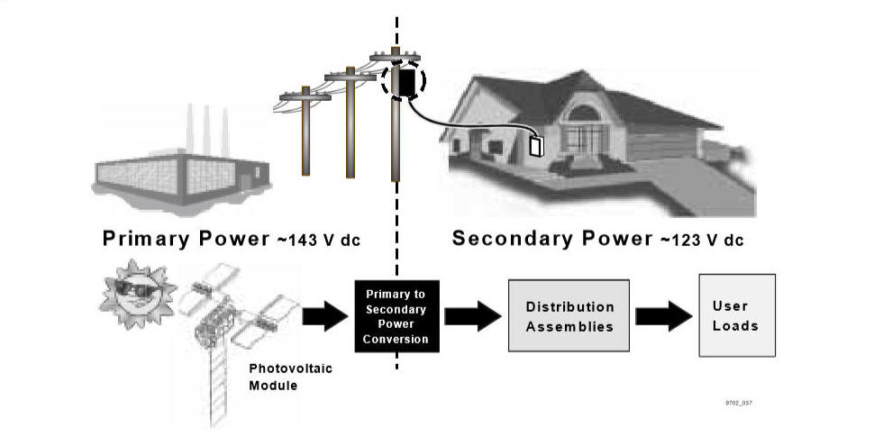
Figure 3-1. Analogy between
municipal electric utilities and ISS EPS
· High voltage power or “primary power” is generated in a
centralized power plant and distributed throughout the area via transmission
lines.
· Before power is delivered to users, the voltage is
stepped down by a transformer to the user required regulated voltage level.
· “Secondary power” (power transmitted at the user-required
voltage level) is distributed to nearby locations and is further divided and
routed by distribution boxes to provide electricity to many individual users.
An analogous process is used on ISS. USOS EPS design
incorporates modules (called Photovoltaic Modules (PVMs)) that are dedicated to
generating and storing power. These
modules or “power plants” provide two sources of primary power (~160 V dc)
called power channels. During both
insolation and eclipse, each power channel provides a continuous supply of power
for distribution throughout ISS.
Primary power is then converted to secondary power (~124 V dc) in proximity to
its intended users. From the converters, secondary power is distributed along a
variety of paths to individual ISS power users.
This two-level power system allows EPS to compensate for factors such as
line losses, hardware degradation, and solar array aging within the primary
power system while providing consistent secondary voltage for ISS users. Per
this distributed design, primary power is used when transmission over
significant distances is required and secondary power is for distribution
locally.
The distributed design of the USOS EPS architecture
provides for the incremental buildup of the power system during ISS assembly.
The PVMs are independent power plants that add to the primary power
production capability. The Secondary Power System, on the other hand, is a local
power network that is integrated into the trusses, modules, and racks of the ISS.
Thus, the Secondary Power System network expands with each ISS assembly stage to
provide new components with power access.
At Assembly Complete, there will be four PVMs (and eight
power channels), which are identified in
Figure 3-2.
Figure 3-2. ISS at assembly
complete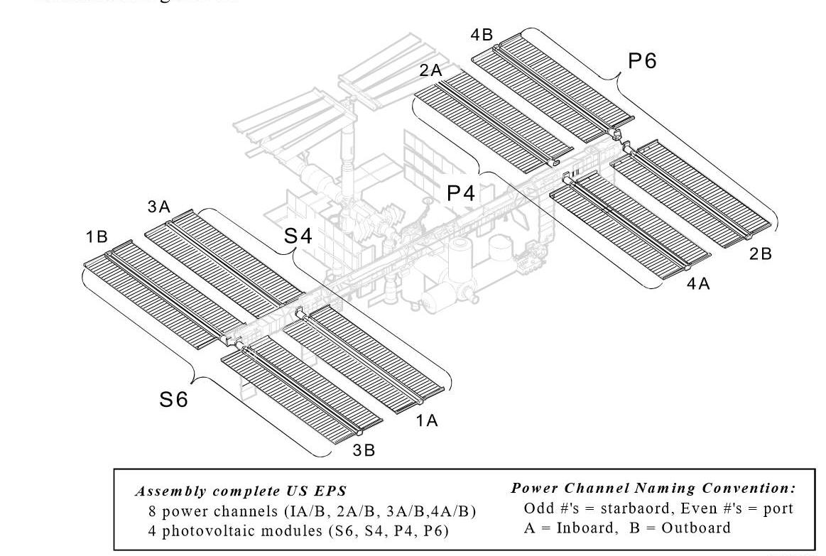
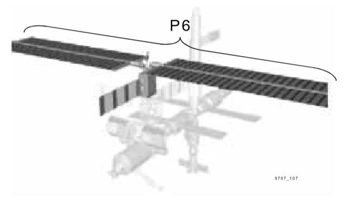
For the Flight 8A scope of this manual, all USOS EPS
primary power is provided by the P6 PVM. The P6 PVM arrives on Flight 4A.
As shown in Figure 3-3, the P6 PVM is
temporarily located on the Z1 truss until it is moved to its Assembly Complete
location on the lateral truss at Flight 13A (see
Figure 3-2). Secondary Power
System components are located on the P6 PVM, Z1 truss, S0 truss, Node 1, PMAs,
Airlock and Lab at Flight 8A.
From the previous description, five core functions can be
identified as necessary to achieve the function of the EPS:
· Generate primary power
· Store primary power
· Distribute primary power
· Convert primary to secondary power
· Distribute secondary power to users.
In addition, there are three support functions that must be
accomplished:
· Thermal control of EPS components
· Grounding of EPS components and ISS
· Managing and controlling the EPS components and
power/energy management.
These USOS EPS functions have been loosely grouped into
three main subsystems: Primary
Power System, Secondary Power System, and support systems.
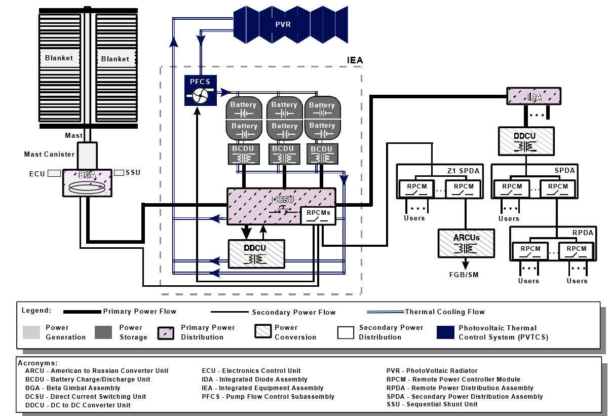
The entire power system, except for grounding and control, are
illustrated in Figure 3-4.
The following sections briefly describe each of the three main
subsystems, as well as their functions and components.
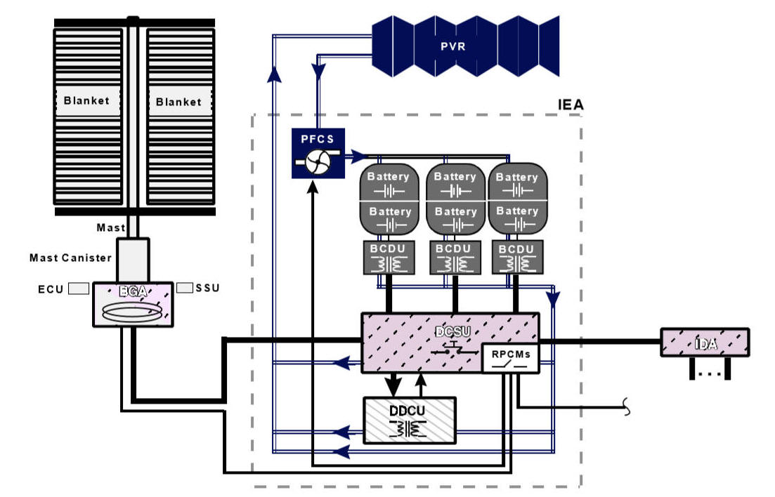
Figure 3-4. USOS EPS schematic
The basic building block of the USOS EPS Primary
Power System architecture is the power channel, which is a group of hardware
components, beginning with a solar array, that are responsible for providing an
independent primary power source.
At this assembly stage, the entire Primary Power System can
be described in terms of a power channel as illustrated in
Figure 3-5.
The following components comprise a power channel:
· Solar Array Wing (SAW), including two Photovoltaic (PV)
blankets, the right and left blanket boxes, mast, and mast canister
· Sequential Shunt Unit (SSU)
· Beta Gimbal Assembly (BGA)
· Electronics Control Unit (ECU)
· Direct Current Switching Unit (DCSU)
· Three Battery Charge/Discharge Units (BCDUs)
· Three battery assemblies (Two-battery Orbital Replacement
Units (ORUs)/assembly).
Though Dc to Dc Converter Units (DDCUs) are generally
associated with the Secondary Power System, each power channel also includes a
DDCU to provide secondary power for IEA components.
Figure 3-5. USOS EPS power channel
A PVM contains all the components for two power channels;
i.e., two sets of PV blankets (see Figure 3-3)
and correspondingly two identical sets of power channel hardware.
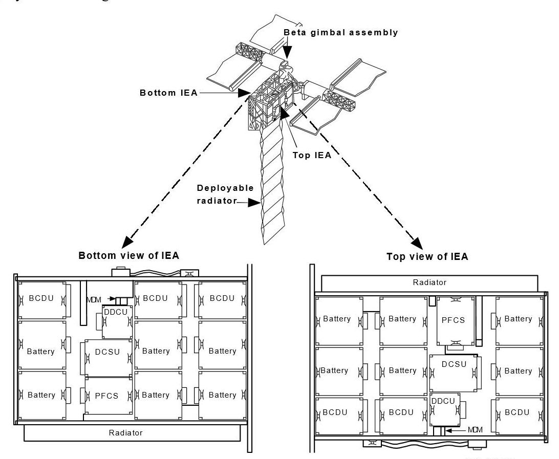
This hardware is
mounted on the Integrated Equipment Assembly (IEA).
The IEA, indicated in
Figure 3-6, is the truss framework that structurally and electrically
integrates the PVM for on-orbit operations. Power channel and support equipment
for the two respective power channels are mounted on the “top” and “bottom” of
the IEA. The IEA structure also
provides integrated cold plates and coolant loops for use by the Photovoltaic
Thermal Control System (PVTCS), which is dedicated to removing excess heat from
IEA hardware. The thermal radiator
for PVTCS can be seen in its deployed state in
Figure 3-6.
Figure
3-6. Integrated equipment assembly
3.4.1.1 Primary Power Generation
Power generation onboard ISS includes conversion of solar
energy to electrical energy, as well as the regulation of that electrical
energy. The power generation
function is accomplished by the PV blankets and structural support hardware
(blanket boxes, mast, mast canister), BGA, ECU; and SSU.
The PV blanket is a collection of PV cells wired in series
providing the large light collecting surface required to meet ISS power needs.
A pair of blankets (left and right) constitutes a PV array.
The PV blankets are supported by blanket boxes (which also serve to house
and protect the blankets for launch).
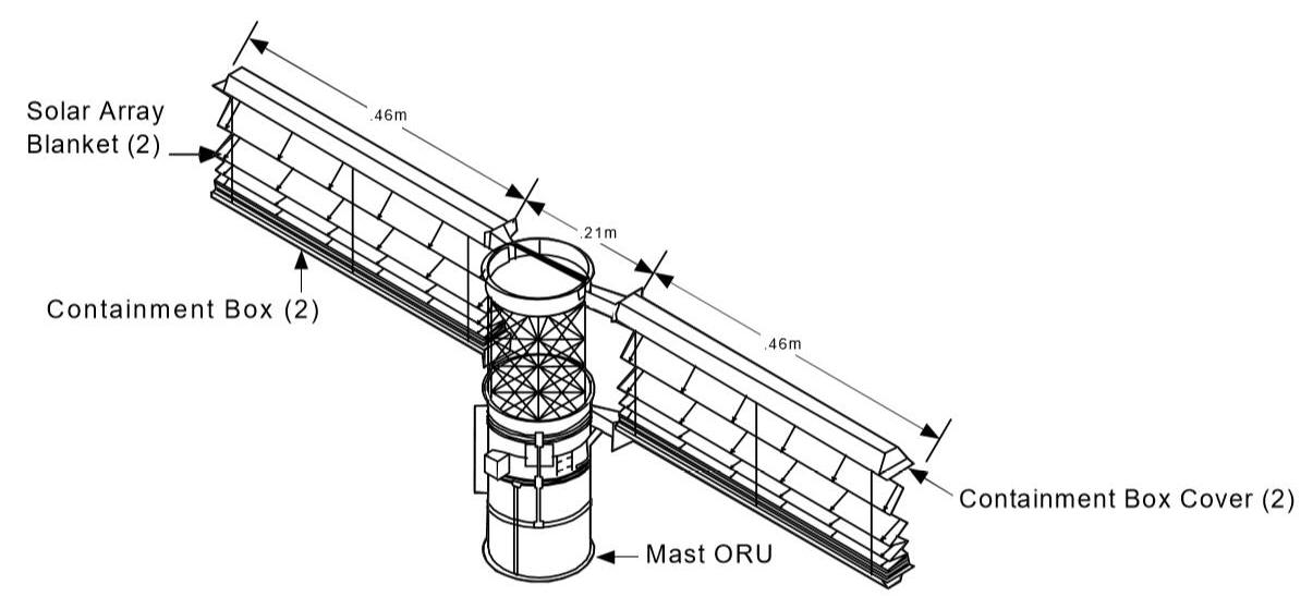
Figure 3-7 shows the
blankets in a partially deployed state.
The blanket boxes are rigidly attached to the mast canister which
provides the housing and extension/retraction mechanisms for the mast that are
used to support the deployed blankets.
In its stowed configuration, the mast is collapsed inside the mast
canister; for deployment, the mast extends to the deploy the array.
The mast, along with the blanket and containment boxes and other
associated hardware, provides the ability to rigidize the deployed PV blankets.
Collectively, the left and right PV blanket and containment boxes, and the mast
canister with mast, are referred to as the Solar Array Wing (SAW).
Figure 3-7. Partially deployed solar array wing
In order to maximize the collection of usable solar energy
in an orbiting vehicle, the PV arrays must be oriented to face the Sun, or more
specifically, to maximize the planar projection of the collection device
relative to the Sun. At Flight 8A,
the Beta Gimbal Assembly (BGA), indicated in
Figure 3-6, is the hardware
providing array orientation. The
BGA provides for rotation of the PV array around its long axis as required to
track the Sun and maximize solar array power production.
The Electronic Control Unit (ECU) located on the BGA is the
command and control link for the power generation function.
The ECU provides power and control for extension and retraction of the
solar array mast, latching and unlatching of the blanket boxes, BGA rotation,
and BGA latching.
Regulation of the array output voltage is required because
of the performance characteristics of PV cells; i.e., output voltage is a
function of the load placed on the cells, resulting in a varying power source
(see Section 2 for further details).
To accomplish this, the Sequential Shunt Unit (SSU) receives power
directly from the PV array and maintains output voltage within a specified range
of 130 V dc to 180 V dc (referred to as “primary power voltage”).
By design, the SSU provides a consistent source of power (typically ~160
V dc), based upon a programmable setpoint.
All EPS equipment or components that use primary power are designed to
accept power within this wide voltage range.
The rationale for regulating power within such a wide range is to account
for:
· Line losses resulting from transferring power across
significant distances on ISS
· Flexibility in regulation to account for downstream
hardware degradation
· Flexibility in regulation to account for hardware aging
(i.e., solar cell aging results in a significant drop in peak output voltage)
· Output voltage of solar cells that vary significantly as
a function of load.
Thus, the SSU considers the above factors, stabilizes the
SAW output voltage based upon a voltage setpoint (typically ~160 V dc) and
relies upon the Secondary Power System to provide consistent, tightly regulated
~124 V dc secondary power to users for the life of the ISS.
The orientation of the energy collection devices and the
regulation of their output voltage are only critical during insolation.
The next segment discusses the power storage function which is required
to provide power during eclipse.
The power storage function is performed by batteries and
BCDUs. The actual storage devices
are Nickel Hydrogen (NiH 2) battery assemblies, each having their own BCDU to
control their State of Charge (SOC).
A battery assembly consists of two battery ORUs connected to a single
BCDU. As seen in Figure 3-5, there
are three battery assemblies and three BCDUs associated with each power channel.
As the name of this function and its associated hardware implies, it is
responsible for storing power throughout the entire orbit. During insolation,
array power is used to charge the batteries.
During eclipse, a portion of the stored battery power is discharged to
supply the ISS. Stored power may
also be used to supplement the power generation function during insolation;
i.e., to satisfy a temporary high power load on the EPS or to supply power in
case there is a failure within the power generation function (including failure
of the SAW orientation function).
With a full complement of batteries (three battery
assemblies/power channel), the storage system is designed to require only a 35
percent depth of discharge to supply the nominal ISS power needs during the
period of orbital eclipse. Given
that the ISS is not exceeding its planned energy consumption, the batteries can
then be fully charged during a single period of insolation.
If the power generation function were to fail, the batteries can supply
power for one complete orbit following a period of orbital eclipse with a
reduced ISS power consumption rate.
The charge and discharge profiles must be carefully controlled to maximize the
life of each of the batteries. The battery SOC determines the recommended
charging profiles used by the BCDUs to regulate the charging of the batteries.
It is important to emphasize that power storage is a
function of the Primary Power System and occurs before the primary power is
converted into secondary power.
This permits a more centralized power storage function (all accomplished on the
PVMs) versus a decentralized power storage function as part of every secondary
power circuit. This centralized
approach results in decreased weight and cost to perform the power storage
function.
The power generation and power storage functions provide
power sources for the Primary Power System, but power flow must be coordinated
between the arrays and batteries, as well as to other components on the IEA and
on to the ISS. This interface is
provided by the power distribution components.
3.4.1.3 Primary
Power Distribution
Primary power distribution for a power channel is the
function of the DCSU. Using a
network of high power switches called Remote Bus Isolators (RBIs), the DCSU
interconnects arrays and batteries to the primary power distribution bus.
During insolation, the DCSU routes power from the arrays to the ISS, as
well as to the BCDUs for battery charging.
During eclipse, the DCSU routes battery power to the ISS to satisfy power
demands. In addition to primary
power distribution, the DCSU has the additional responsibility for routing
secondary power to components on the PVM (e.g., the ECU and other support
components). Note that while the P6
PVM is located on the Z1 truss, secondary power produced on the IEA is also
routed directly to the Z1 truss for distribution.
This secondary power is provided by the DDCU located on the IEA. The DDCU
receives primary power from the DCSU, converts into secondary power and sends it
back to Remote Power Controller Modules (RPCMs) (see next section) for
distribution. The RPCMs are housed
within the DCSU as shown in Figure 3-5.
While the DCSU handles power distribution on the IEA, the
BGA provides for the transmission of primary power from the PV array to the IEA.
The BGA also provides for transmission of secondary power to the ECU.
Although it has no switches to control the flow of power, the BGA
incorporates a roll-ring design to provide conduits for power (and data), while
allowing a continuous 360° rotation.
The DCSU provides one output of primary power from a power
channel. While the P6 PVM is
located on the Z1 truss, further distribution of primary power from power
channels 2B and 4B to various areas of the ISS is accomplished by Integrated
Diode Assemblies (IDAs) located on the Z1 truss (shown
in Figure 3-5). From the IDAs,
primary power is input to the Secondary Power System for conversion and
distribution of power to users. The
Secondary Power System is the subject of the next section.
The Secondary Power System is illustrated in
Figure 3-8.
The first step in the local power distribution is the conversion from
primary power (~160 V dc) to secondary power (~124 V dc). Power conversion
occurs in various areas throughout the ISS, within pressurized modules, on truss
segments, as well as on the IEA, i.e., near wherever users require secondary
power. After conversion, secondary power is distributed through a network of
power distribution assemblies. The
active components within these distribution boxes are remotely commanded
switches that control and monitor the flow of power through the network to
individual users, such as systems, payloads, crew equipment, EPS components,
etc.
Figure 3-8.
USOS secondary power system
3.4.2.1 Secondary Power Conversion
The secondary power conversion function uses one type of
ORU, the DDCU. As the name implies,
the DDCU is responsible for dc power conversion, in this case, primary power
into secondary power using a transformer.
Each DDCU has one primary power input and one secondary power output.
As discussed earlier, the primary power voltage is typically ~160 V dc
but can vary over a wide range, while the output is specified to be ~124 V dc,
which is the prescribed voltage for all users of the Secondary Power System.
If any other voltage level is required by user loads, (e.g., payloads or
crew equipment) then it is the responsibility of the user to perform the
conversion from ~ 124 V dc to the required voltage.
3.4.2.2 Secondary Power Distribution
The workhorse of the secondary power distribution system is
the RPCM, an ORU, which contains solid-state or electromechanical relays, known
as Remote Power Controllers (RPCs). These switches can be remotely commanded to
control the flow of power through the distribution network and to the users.
There are different types of RPCMs, resulting from varying numbers of
RPCs and varying power ratings. As
shown in Figure 3-8, secondary
power originates in a DDCU and is then distributed through a network of ORUs
called Secondary Power Distribution Assemblies (SPDAs) and Remote Power
Distribution Assemblies (RPDAs).
SPDAs and RPDAs are essentially housings that contain one or more RPCMs; the
designation, either SPDA or RPDA, refers to the level of hierarchy within the
distribution system As a general
rule, the hierarchy dictates that DDCUs feed power to SPDAs, which either
provide power to one or more user loads or RPDAs.
RPDAs, in turn, feed power to one or more user loads.
Note that RPCMs have only one power input; thus, if power is lost at any
level of the Secondary Power System, all downstream user loads will be without
power. As mentioned previously,
there is no redundancy in the Secondary Power System; rather, redundancy is a
function of the user’s loads. For
example, a critical user load may be able to select between two input power
sources that use different power channels and thus different secondary power
paths.
As with DDCUs, SPDAs and RPDAs may be located internally or
externally. Depending on their
specific location, SPDAs and RPDAs may interface with EETCS or use heat pipes
where EETCS is not available.
Recall that RPCMs are also located within the DCSU on the IEAs to provide
distribution and control of secondary power to power channel components, as
required.
In addition to functions, such as power production,
storage, conversion, and distribution, other supporting functions must be
incorporated into the architecture to maintain the USOS EPS.
USOS EPS Photovoltaic Modules (PVMs) are designed with
their own Photovoltaic Thermal Control System (PVTCS).
This is necessary because at Assembly Complete, all PVMs are separated
from the ISS by 360° rotating Solar Alpha Rotary Joints (SARJs) which pass power
and data, but not fluids. Thus,
PVMs cannot interface with the ISS Thermal Control System (TCS).
Each power channel has its own independent PVTCS consisting of one Pump
and Flow Control Subassembly (PFCS) ORU and coldplates, coolant lines, and
ammonia coolant which are integrated into the IEA.
PVTCS also includes one Photovoltaic Radiator (PVR) per IEA, shown in
Figure 3-3, which is shared by the two power
channels on a PVM. It is important
to note that although the two PVTCS cooling loops share a common PVR, the
cooling lines do not intersect and thus the PVTCS operate independently.
Another important factor in the design of the EPS is the
grounding scheme to minimize arcing and shock hazards.
The grounding function is incorporated in the Single Point Ground (SPG)
architecture that maintains all components on the ISS at a common potential.
SPG refers to grounding such that all the structures and components
within the USOS are electrically tied to a common point (the metal
infrastructure of the ISS), minimizing electrical shock hazards to the crew and
equipment. Another potential shock
hazard exists when equipment such as personal computers are connected to Utility
Outlet Panels (UOPs). To eliminate
this hazard, Ground Fault Interrupters (GFIs) are installed on all utility
outlet panels to detect short circuits and disconnect equipment from the power
source.
Although the SPG architecture maintains all components of
the USOS EPS at a common potential, this potential may not correspond to the
surrounding space environment. As
it turns out, the potential difference between the ISS structure and the plasma
environment in orbit could be as much as ~140 V dc during insolation.
This difference in potential can result in microarcing between the space
environment and the ISS structure, potentially damaging the arrays or thermal
coating that covers the ISS. To
minimize this potential difference, Plasma Contactor Units (PCUs) located on the
Z1 truss (one operational and one backup) generate plasma from Xenon gas and
emit a stream of electrons into space.
This electron emission results in a “grounding-strap” that effectively
grounds the ISS to the space environment, minimizing the potential difference as
well as related hazards to the ISS and crew.
Operating behind all of these before-mentioned functions,
four tiers of command and control units/applications work to monitor and control
the operation of the USOS EPS.
Command and control of the USOS EPS is provided by software applications and
hardware which provides system monitoring and reconfiguration capabilities from
both onboard and the ground. The
onboard capability allows the crew to determine system status and provides any
required reconfiguration for systems operations.
Ground control and monitoring is required to support ISS EPS operations,
analysis, and planning.
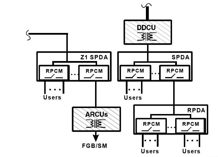
Figure 3-9. Structure of EPS
command and control tiered architecture
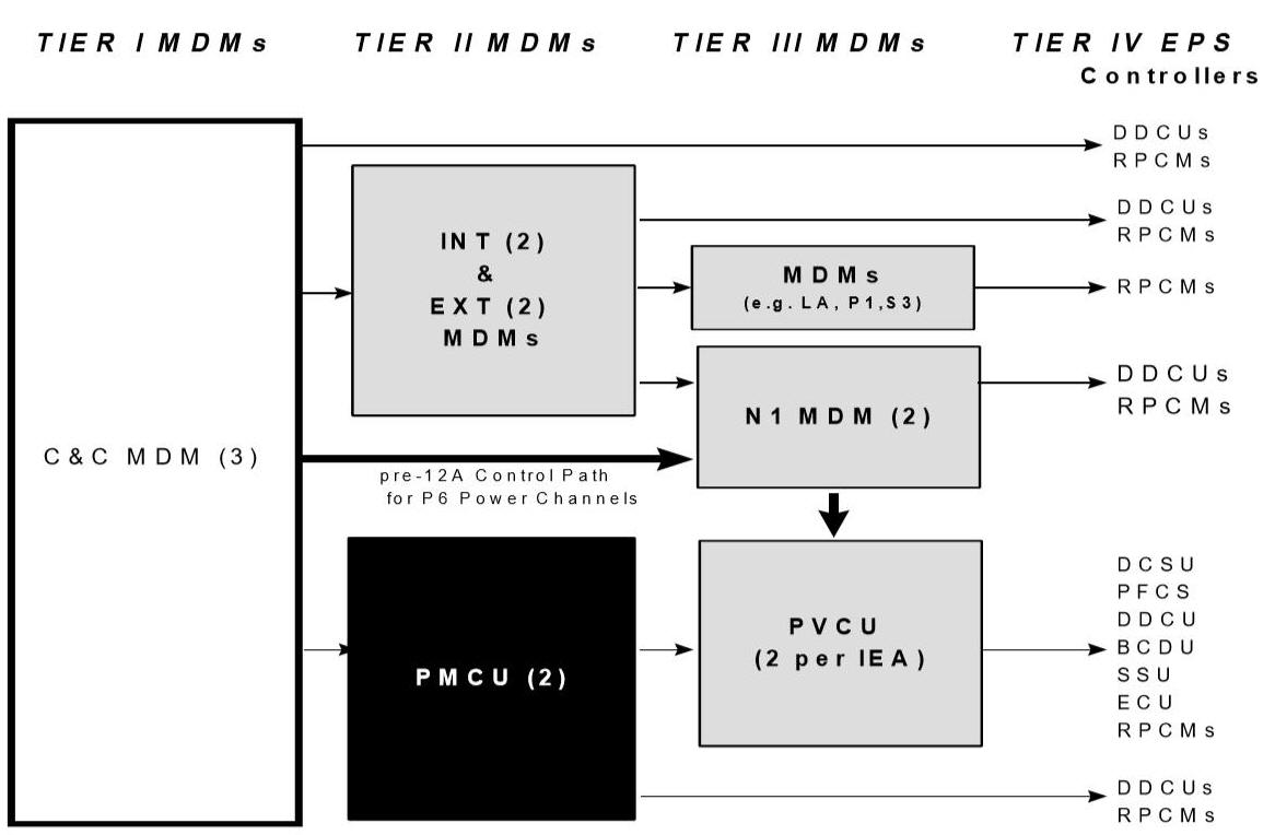
The tier structure and example responsibilities of the
command and control ORUs are illustrated in
Figure 3-9.
Command and control functions for the top three tiers are performed by
computers or Multiplexer/Demultiplexers (MDMs).
Tier 1 control is a function of the Command and Control (C&C) MDM
(located in the Lab) through which both crew and ground interface all command
and control functions. Most of the
EPS functionality at the Tier 2 level, is performed by the Power Management
Control Unit (two located in the Lab, one backup) and the Node 1 MDM, although
other MDMs may have control of particular DDCUs and RPCMs.
At this assembly stage, the Tier 3 Node 1 MDM’s have Tier 2
responsibilities, including controlling the Tier 3 Photovoltaic Control Units
(PVCUs) located on the P6 PVM.
Although there is one PVCU per power channel (PVCU-2B, PVCU-4B), one PVCU
controls the operations of both power channels on the PVM with the other as
backup. Note that the MDMs are
generally in close proximity to the equipment for which they are responsible.
Tier IV consists of firmware controllers responsible for controlling
component functions and providing telemetry to higher tiers.
3.4.4 USOS EPS Redundancy and
System Protection
Thus far, the architecture of the USOS EPS has been
discussed in terms of how power is provided to ISS users.
But equally important functions of the system architecture are redundancy
and fault protection.
Each of the power channels are preconfigured to supply
power for particular ISS loads; however, to provide for power source redundancy,
the assembly complete design provides for rerouting (i.e., cross-strapping)
primary power between various power channels, as necessary.
At Assembly Complete, the USOS EPS will have four PVMs containing eight
SAWs and correspondingly eight power channels (shown in
Figure 3-2) with full
cross-strapping capability. However, through Flight 8A, there is only one PVM
and no cross-strapping capability (refer to Section 2).
It is important to note that only primary power can be cross-strapped.
Once power is converted into secondary power, power flow through the
distribution network cannot be rerouted. As a result, if there is a failure
within the Secondary Power System, there is no redundancy, and the entire
downstream path from the failure is unpowered.
Instead, redundancy is generally determined by user loads.
Examples are:
· The component may swap between multiple power input
sources
· Multiple components perform the same function; thus, the
responsibilities of one component are assumed by another
· Multiple components work
together to perform a function with the loss of a component, resulting in
degraded operational capabilities.
Details concerning hardware redundancy within EPS
components is discussed in Section 2.
System protection encompasses the architecture’s ability to
detect that a fault condition has occurred, confine the fault to prevent
damaging connecting components, and execute an appropriate recovery process to
restore functionality, if possible.
This process is usually referred to as Fault Detection, Isolation, and Recovery
(FDIR). For example, upon detection
of a fault, components can be isolated, thereby preventing propagation of
faults. In response to overcurrent
conditions, the architecture is designed such that each downstream circuit
protection device is set to a lower current rating and responds more quickly
than the protection device directly upstream. This ensures that electrical
faults or “shorts” in the System do not propagate toward the power source.
Another function of the architecture’s system-protection shuts down the
production of power when array output voltage drops below a specified
lower-limit threshold. This
prevents the Photovoltaic (PV) cells from operating in low-voltage, high-current
applications, causing cell overheating.
In summary, all the various implementations of system-protection work
together to isolate faults or shorts at the lowest level.
This approach minimizes impacts to the users of the EPS and also protects
the EPS from complete failure from low-level faults.
More details concerning redundancy, system protection, and
FDIR are contained in the description of individual components in the ISS
Electrical Power System Training Manual.
The following section describes the USOS EPS interfaces
with other systems and power sources.
In addition to the power sources inherent to the USOS EPS,
other power sources from the ROS, including the FGB and SM, as well as the
Shuttle, are required to support various phases of assembly and ISS operations.
Thus, power interfaces are required to allow transferring power among the
USOS, the ROS, and the Shuttle.
3.5.1.1 Russian -
American Power Interface
According to operational agreements, ROS power will support
USOS operations early in the Assembly Phase.
However, power conversion is required because the user-voltage level
required by the USOS is ~124 V dc and the FGB EPS provides power at ~28 V dc.
This function is accomplished by the Russian-to-American Converter Unit
(RACU). Similarly, per operational
agreements, USOS will provide power to the ROS, which also requires conversion.
The American-to-Russian Converter Unit (ARCU) transforms the ~124 V dc
power produced by the USOS EPS into the ~28 V dc power for use by the FGB EPS.
Both the ARCUs and RACUs, located on the FGB and SM, are under Russian
command authority.
3.5.1.2 Shuttle Power Conversion
The USOS EPS will also be supported by the Shuttle when it
is docked to the ISS. Although the
Shuttle power system generates ~28 V dc, Assembly Power Converter Units (APCUs)
located in the Shuttle payload bay can provide either primary (~140 V dc) or
secondary (~124 V dc) voltage per the requirements for the particular mission.
However, the voltage level is reconfigured on the ground and cannot be
changed on orbit. For example, the
APCU is configured to output primary power for Flight 4A to support power
channel startup operations but configured to output secondary power for the MPLM
on its Shuttle flights. Commanding
of the APCU (on/off) is performed by the Shuttle crew on orbit.
In addition to power interfaces, USOS EPS has interfaces
with other systems, both to provide power or receive necessary data or services.
Recalling the discussion of the Secondary Power System, note that all
systems that require power from USOS EPS must interface with the Secondary Power
System and a specific RPC (except for some EPS components that use primary
power). The following sections
describe the USOS EPS interfaces for receiving data or services from USOS
systems.
3.5.2.1 Guidance, Navigation and Control
To orient the arrays, the Guidance, Navigation and Control
(GNC) MDM broadcasts target angles for the BGAs.
This data is routed through the Node 1 MDM to the PVCU.
The PVCU then commands the BGA to the proper orientation.
3.5.2.2 Command and Data Handling
Command and Data Handling (CDH) provides all MDMs, data
processors, and data buses required for the execution environment of the EPS
software applications providing the control and monitoring functions.
Supporting the software execution environment not only includes the data
processing, but also the data communications.
Data communications includes the transmission of commands, status, and
data parameters required to monitor and control the EPS.
3.5.2.3 Thermal Control System
Where possible, USOS EPS components interface with the ISS
TCS (ETCS or EETCS for external components and ITCS for internal components) for
thermal control. However, on the
PVMs and the Z1 truss, ISS TCS is not available.
Consequently, PVMs use PVTCS for active thermal control of IEA
components, and DDCUs, SPDAs, and RPDAs located on the Z1 truss use heat pipes
for passive cooling.
3.6 Comparison between USOS
and ROS EPS
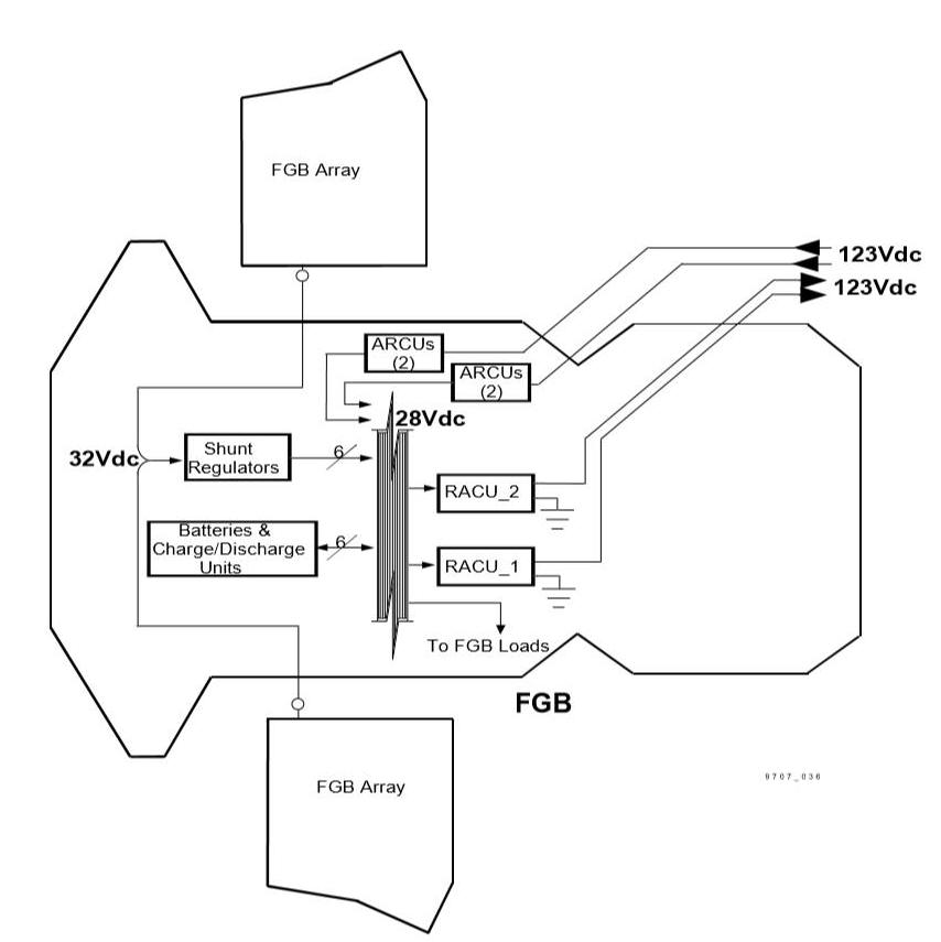
For comparison purposes, consider
Figure 3-10, which illustrates
the EPS of the FGB. (FGB is used as
a representative example of ROS EPS architecture.).
In contrast to the USOS EPS distributed system design, the FGB uses a
localized architecture. Instead of
producing power in PVMs and distributing that power throughout multiple modules
as in USOS EPS, the FGB and SM have self-contained EPS within each module (i.e.,
the FGB and SM modules produce, store, and consume their own power).
However, the power system components are similar: solar arrays, array
output regulators, batteries, charge/discharge units, and a distribution system.
Furthermore, the voltage produced by the Russian arrays is converted to a lower
user voltage level (32 V dc to 28 V dc), although this differs from the USOS EPS
voltage levels (160 V dc to 124 V dc).
ARCUs and RACUs provide the power interface between the USOS and ROS EPS
by compensating for the different voltage levels.
Another less apparent difference is that the ROS EPS uses a floating
ground rather than the SPG, as in the USOS EPS.
For the floating ground, equipment chassis are connected to the ISS
infrastructure. However, individual
components may not be; thus, all components may not be at a common potential.
Figure 3-10.
FGB electrical system drawing
A common question in regard to system design involves the
choice of the USOS operating voltage level of ~124 V dc compared with the more
common ~ 28 V dc currently used on the Shuttle, FGB, and the MIR space station.
Part of the reason lies in the scope of the ISS, including the associated
power requirements and the use of a distributed EPS architecture. Considering
that power is a function of voltage and current, at low voltages, high power
requires large currents. Large
currents require heavy, thick conductors and have associated line losses. Use of
a higher voltage level (near the USOS commercial standard 120 V ac) addresses
the issues of cost, weight, and power loss for the USOS EPS.
Both the ROS and USOS EPS have the capability and
responsibility for providing continuous electrical power to the ISS.
Although the ROS and USOS EPS are similar in functionality, the FGB and
SM are designed with self-contained EPS, while the USOS uses a distributed
approach. The USOS EPS continuously generates primary power on PVMs and
transmits it into the vicinity of the power user, converts into secondary power,
and distributes power to each local user.
On Flight 8A, shown in Figure
3-11, USOS power production capability is provided by the P6 PVM.
During this assembly stage, ISS power is provided by P6 arrays, FGB
arrays, and SM arrays. Note that
APCU power is also available when the Shuttle is docked to the ISS.
Figure 3-11. ISS at 8A
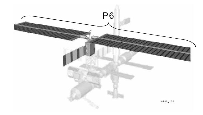
Table 3-1 provides a summary of the functions and components discussed in
this overview that accomplishes the USOS EPS function.
It is important to emphasize the two areas not addressed in this table:
· System protection, which is distributed across the USOS
EPS in the form of software and hardware sensing of fault conditions and
reactions to isolate faults and minimize system impacts
· System grounding design, which ties all components to a
common potential.
Through the scope of this manual, the functions of the
Primary Power System are accomplished by power channel components.
Through the Flight 4A-12A period, all USOS EPS power is provided by two
power channels on the P6 PVM. This
power is transmitted directly to Secondary Power System components throughout
the USOS segment, where it is converted to the proper voltage level and
distributed to ISS users.
Table 3-1. USOS EPS
components at flight 8A
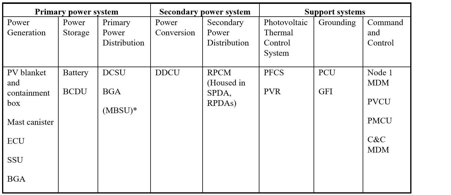
*Four MBSUs are located on the S0 truss segment by Flight
8A but not integrated into the USOS EPS.
Additional power sources from the ROS and Shuttle are
necessary for the assembly and operation of the ISS.
These power sharing interfaces employ converters to compensate for
voltage differences between the following electrical systems:
· APCU for interfacing between USOS EPS and Shuttle
· ARCU and RACU for interfacing between USOS EPS and ROS
EPS