6 Environmental Control and
Life Support System Overview
6 Environmental Control and
Life Support System Overview
Figure 6-1. ECLSS Subsystem interfaces at
Flight 8A
6.3.1 Atmosphere Control and
Supply
Figure 6-2, the ECLSS USOS Atmosphere
Control and Supply Subsystem
6.3.1.1
USOS Atmosphere Supply, Distribution, and Control
6.3.1.3 Pressure Equalization
Between Modules
6.3.1.4 Additional Atmosphere
Control and Supply Capabilities at Assembly Complete
6.3.2 Atmosphere
Revitalization
Figure
6-3 ECLSS Functional Overview USOS Atmosphere Revitalization Subsystem and its
Interfaces
6.3.2.1 Major Constituent
Monitoring
6.3.2.2 Carbon Dioxide
Removal
6.3.2.3 Trace Contaminant
Control
6.3.2.4 Additional Atmosphere
Revitalization Capabilities at Assembly Complete
6.3.3 Temperature and
Humidity Control
Figure 6-4 ECLSS Functional Overview
Temperature and Humidity Control Subsystem
6.3.3.2 Intramodule
Ventilation
6.3.3.3 Intermodule
Ventilation
6.3.4 Fire Detection and
Suppression
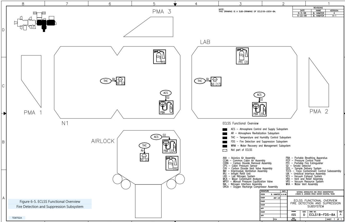
Figure 6-5, ECLSS Functional Overview
Fire Detection and Suppression Subsystem
6.3.4.4 Supplemental Oxygen
Supply
6.3.4.5 Additional Fire
Detection and Suppression Capabilities at Assembly Complete
6.3.5 Water Recovery and
Management
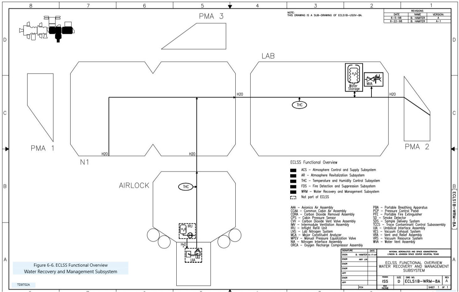
Figure 6-6, ECLSS Functional Overview
Water Recovery and Management Subsystem
6.3.5.1 ROS Water Recovery
and Management Overview
6.3.5.2 USOS Water Recovery
and Management
6.3.5.3 Additional Water
Recovery and Management Capabilities at Assembly Complete
Figure 6-7. ECLSS interfaces at Flight 8A
6.5.1 Flight 1A/R -
Functional Cargo Block
6.5.3 Flight 1R - Service
Module
6.6.1 ECLSS Purpose and
Functions
6.6.2 Subsystem Names and
Functions
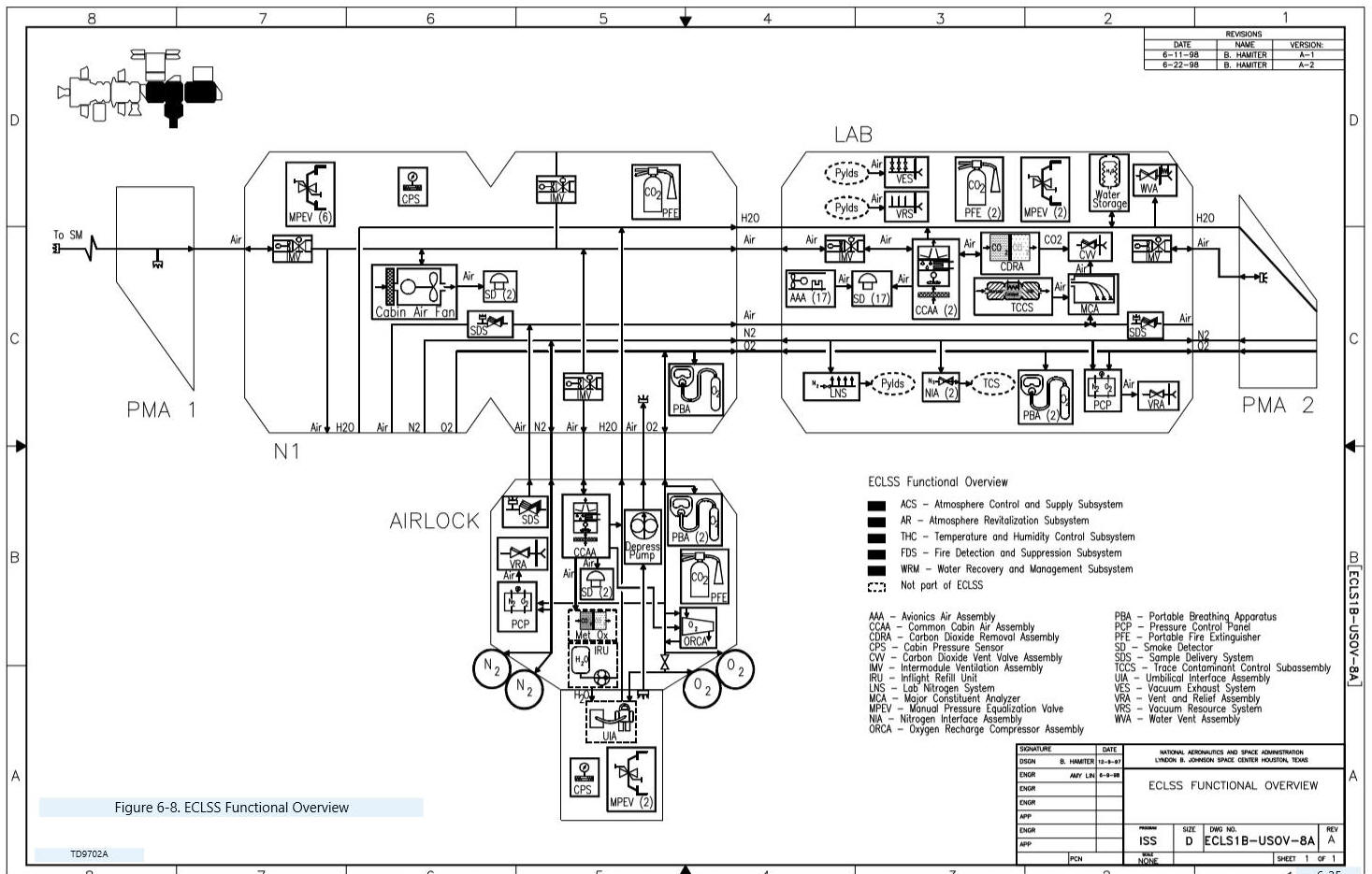
Figure 6-8 shows how all the components
of the subsystems interact with each other.
6 Environmental Control and
Life Support System Overview
The Environmental Control and Life Support System (ECLSS)
maintains a pressurized habitable environment, provides water recovery and
storage, and provides fire detection and suppression within the International
Space Station (ISS). This segment
includes an overview of ECLSS and its component subsystems.
It also describes the relations between subsystems, and between ECLSS and
other Station systems.
After completing this section, you should be able to:
· Describe the major functions provided by ECLSS and each
of its subsystems
· Identify major ECLSS hardware components and state their
function and general functional redundancies
· Identify major ECLSS functional dependencies on the
Thermal Control System, Electrical Power System, and Command and Data Handling
System
· Identify major functional support provided by ECLSS for
the Thermal Control System, Payloads, Crew Health Care System, and
Extravehicular Activity System
· Describe major responsibilities and milestones of the
United States Orbital Segment (USOS) and Russian Orbital Segment (ROS) through
8A, as well as the USOS added capabilities at Assembly Complete.
The Environmental Control and Life Support System (ECLSS)
provides a pressurized and habitable environment within the Space Station by
supplying correct amounts of oxygen and nitrogen, controlling the temperature
and humidity, removing carbon dioxide and other atmospheric contaminants, and
monitoring the atmosphere for the presence of combustion products, and major
constituent proportions. The system
also collects, processes, and stores water and waste used and produced by the
crewmembers, and provides fire detection, suppression, and crew safety
equipment.
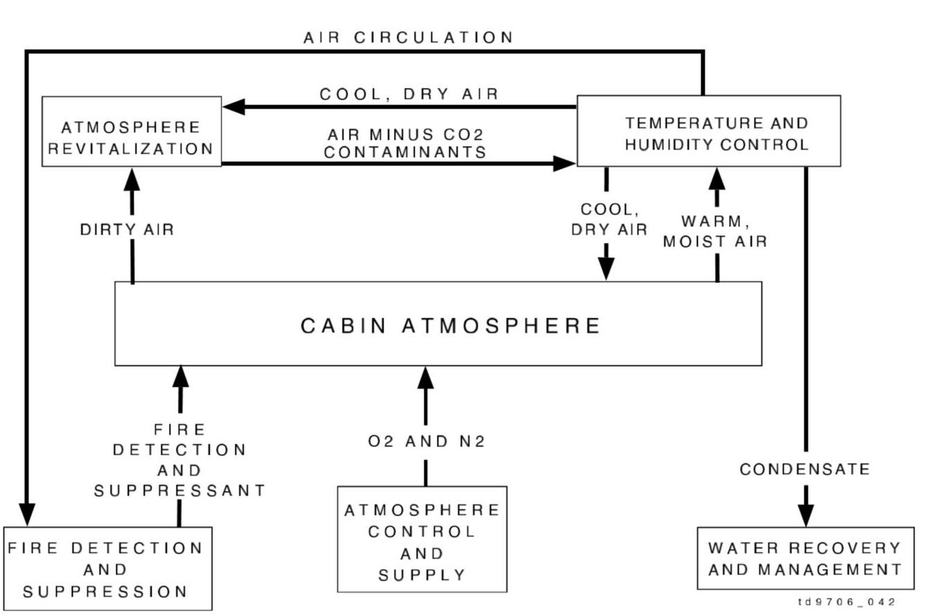
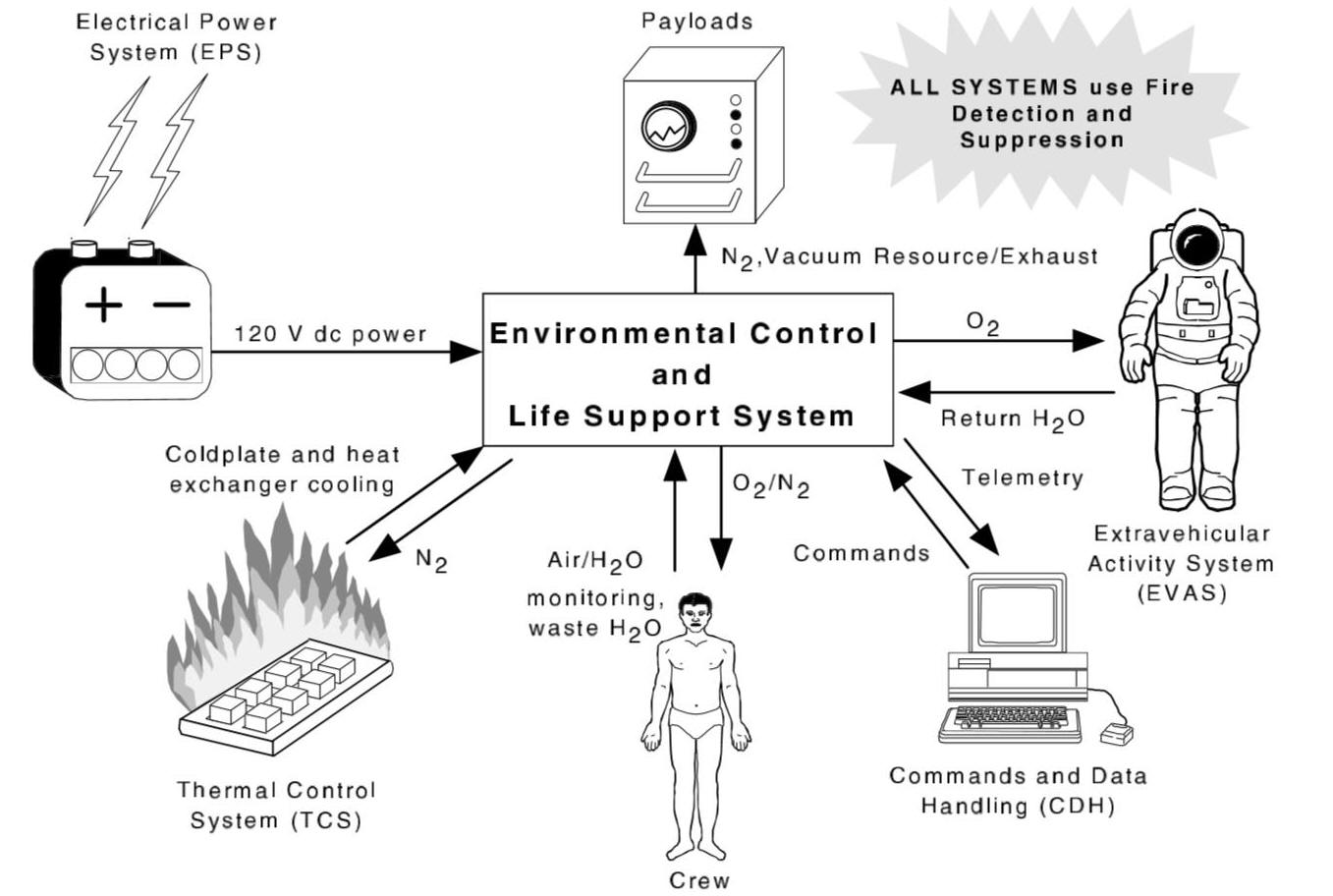
The general functions of the five major subsystems of USOS
ECLSS at Flight 8A are shown in
Figure 6-1. As illustrated, the
primary ECLSS concern, whether directly or indirectly, is with the ISS
atmosphere. This section of the ISS
Familiarization Manual presents ECLSS through its five subsystems:
Atmosphere Control and Supply, Atmosphere Revitalization, Temperature and
Humidity Control, Fire Detection and Suppression, and Water Recovery and
Management.
Figure 6-1. ECLSS Subsystem
interfaces at Flight 8A
6.3.1 Atmosphere Control and
Supply
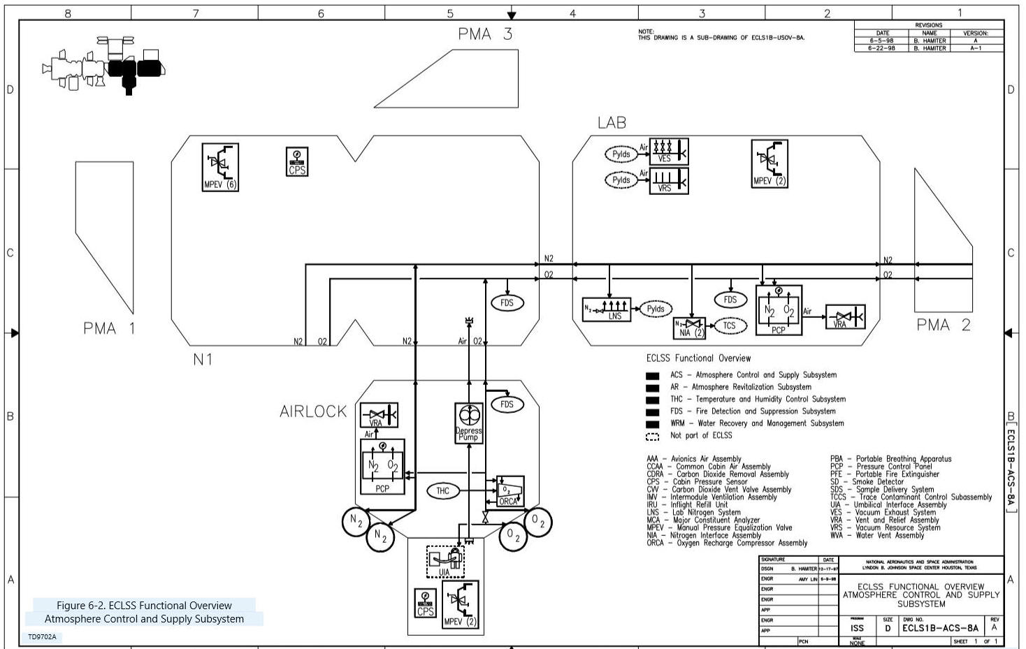
In Figure 6-2,
the USOS Atmosphere Control and Supply Subsystem and its interfaces are
illustrated for a Flight 8A configuration.
This subsystem provides oxygen and nitrogen to maintain the Space Station
atmosphere at the correct pressure and composition for human habitation.
The Atmosphere Control and Supply Subsystem also provides gas support to
various users on the Station, as well as pressure equalization and
depressurization capabilities.
Figure 6-2, the ECLSS USOS
Atmosphere Control and Supply Subsystem
The Russian Orbital Segment (ROS) has primary
responsibility for atmosphere control and supply functions at the Flight 8A
configuration. The Progress
resupply vehicle is outfitted with tanks that can be filled with either
nitrogen, air, or oxygen. These
tanks are manually opened by the crew if the cabin pressure is low.
Oxygen for the Station is primarily supplied by an oxygen generator
called the Elektron, which electrolyzes water into hydrogen and oxygen.
Additional oxygen can be provided by a Solid Fuel Oxygen Generator that
uses chemical cartridges to produce oxygen in an exothermic reaction.
6.3.1.1
USOS Atmosphere Supply, Distribution,
and Control
The oxygen and nitrogen gases used by the USOS Atmosphere
Control and Supply Subsystem are provided through the supply, distribution, and
control portions of the subsystem.
Four highpressure gas tanks, two of nitrogen and two of oxygen, are stored on
the exterior of the Airlock. The gases are distributed to the various users by a
plumbed system running throughout the USOS.
Another system of high-pressure plumbing allows the tanks to be recharged
by the Shuttle. An oxygen
compressor housed in the Airlock enables the oxygen tanks to be fully recharged
because the Shuttle does not store oxygen at a high enough pressure to fully
recharge the tanks. Empty tanks can
also be replaced with full tanks as a second resupply option.
The Pressure Control Assembly monitors atmospheric
pressures, controls the introduction of nitrogen and oxygen into the cabin
atmosphere, and provides the means to depressurize Station volumes if required.
The depressurization function is used in standard operations to relieve
atmospheric overpressure, and in emergencies to vent hazardous contaminants
overboard or as a last resort to extinguish a fire.
The Atmosphere Control and Supply Subsystem provides gas
support to several users on the Station besides the atmosphere.
Nitrogen is used to pressurize the Internal Thermal Control System
accumulators and to calibrate the Crew Health Care System Volatile Organic
Analyzer. The biggest users of nitrogen resources are the Payloads.
A minor subsystem of ECLSS, the Vacuum System, is included here because
its Payload support functions are similar to those of the Atmosphere Control and
Supply Subsystem. The nitrogen
provided to payload user via the vacuum system has vacuum resource and exhaust
capabilities. Oxygen is provided
for Extravehicular Activities (EVAs) and to the Fire Detection and Suppression
Subsystem Portable Breathing Apparatus (PBA).
The Airlock Depressurization Pump also supports normal EVA activities by
pumping most of the Crew Lock air into Node 1 before the crew egresses.
6.3.1.3 Pressure Equalization
Between Modules
The Atmosphere Control and Supply Subsystem also provides
Manual Pressure Equalization Valves to equalize pressure between Space Station
modules while the hatch is closed.
A valve on each USOS hatch permits pressure equalization as modules are added to
the Station, during normal EVA activities, or in the event that a module has
been isolated in a contingency procedure.
There are similar pressure equalization devices on the ROS hatches.
6.3.1.4 Additional Atmosphere Control and Supply Capabilities at Assembly
Complete
At Assembly Complete, the Atmosphere Control and Supply
Subsystem will have the addition of an oxygen generator on the USOS and the
Sabatier on the ROS. The Sabatier
conserves Station resources by producing water through reaction of hydrogen from
the Elektron with carbon dioxide from the Atmosphere Revitalization Subsystem.
At Assembly Complete, Atmosphere Control and Supply will also provide
oxygen to the Water Recovery and Management Subsystem Potable Water Processor to
assist in the purification of Station water.
6.3.2 Atmosphere
Revitalization
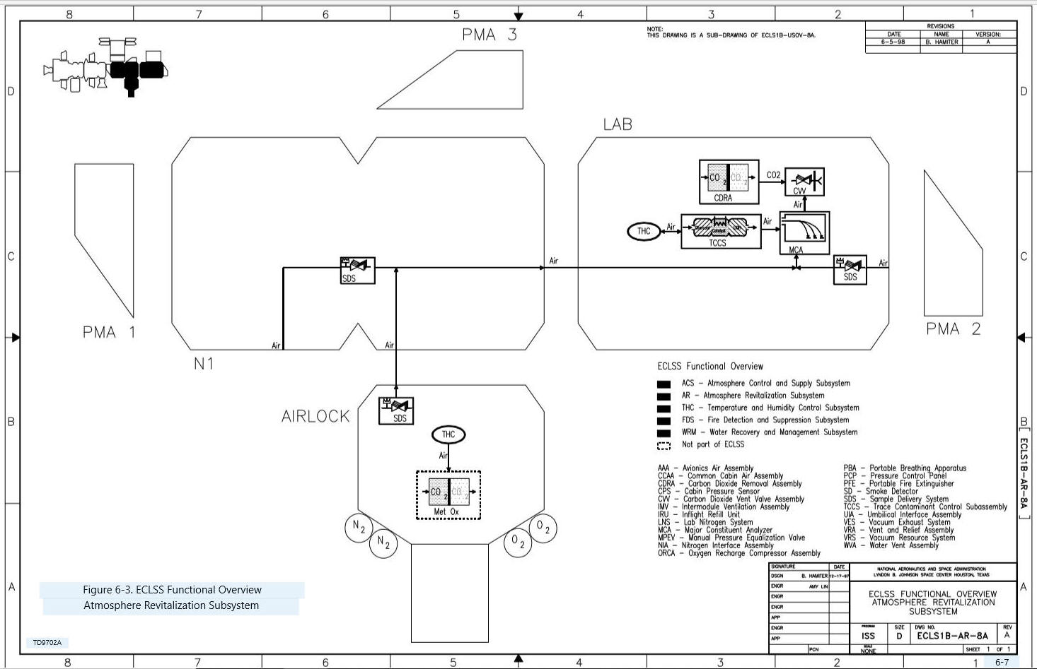
Figure 6-3
shows the USOS Atmosphere Revitalization Subsystem and its interfaces.
This subsystem ensures that the atmosphere provided by the Atmosphere
Control and Supply Subsystem remains safe and pleasant to breathe.
It performs carbon dioxide removal,
trace contaminant control, and major atmospheric constituent monitoring.
Figure 6-3 ECLSS Functional Overview USOS
Atmosphere Revitalization Subsystem and its Interfaces
6.3.2.1 Major Constituent
Monitoring
The Major Constituent Analyzer monitors the composition of
the Station atmosphere by mass spectrometry.
Measurements are used to control the addition of oxygen and indirectly,
nitrogen, into the Station atmosphere by the Atmosphere Control and Supply
Subsystem, and to monitor the performance of the assembly that removes carbon
dioxide. In the ROS, the Gas Analyzers use several different gas detection
methods to provide similar functions.
Air is delivered to the Major Constituent Analyzer by a network of pipes,
valves, and sample ports running throughout the USOS.
This network is the Sample Delivery System.
6.3.2.2 Carbon Dioxide
Removal
The Carbon Dioxide Removal Assembly (CDRA) collects carbon
dioxide from the cabin atmosphere with a series of regenerable sorbent beds and
expels the unwanted gases to space.
To remove carbon dioxide effectively, the CDRA requires cold, dry air, so it
receives air from the Temperature and Humidity Control Subsystem and interfaces
directly with the Internal Thermal Control System Low Temperature Loop.
On the ROS, the Vozdukh performs the same function as the CDRA.
Lithium hydroxide-based canisters are available for backup ROS
functionality.
6.3.2.3 Trace Contaminant
Control
The Trace Contaminant Control Subassembly filters and
catalyzes numerous gaseous contaminants and odors from the cabin atmosphere.
These contaminants are caused by material off-gassing, leaks, spills, or
other events. On the ROS, the Trace
Contaminant Control Unit operates similarly to the Trace Contaminant Control
Subassembly. The Harmful Impurities
Filter provides backup contaminant control as needed.
6.3.2.4 Additional Atmosphere
Revitalization Capabilities at Assembly Complete
At Assembly Complete, the USOS adds duplicates of each of
the Major Constituent Analyzer, Carbon Dioxide Removal Assembly (CDRA), and
Trace Contaminant Control Subassembly. These duplicates will serve as backup
only, because each device operates at a three-person rate. The ROS has similar
capabilities which will be used in conjunction with the USOS equipment, and
together they will be sufficient to support a six-member crew.
6.3.3 Temperature and
Humidity Control
Figure
6-4 shows the USOS Temperature and Humidity Control Subsystem and its
interfaces. This Subsystem helps maintain a habitable environment within the
Station atmosphere by circulating cool dry air, removing humidity and
particulates, and maintaining the temperature.
Circulation of the atmosphere minimizes temperature variations, ensures
homogeneous atmospheric composition, and provides a means for smoke detection.
Three levels of circulation are provided:
rack, intramodule, and intermodule ventilation.
Rack ventilation cools and circulates air within an individual rack.
Intramodule ventilation provides circulation to ensure a consistent
atmosphere within a single module, and may support cooling and humidity removal.
Finally, intermodule ventilation circulates air between modules to ensure
a homogeneous atmosphere throughout the Station.
While the ROS equivalent of Temperature and Humidity Control equipment is
considered a part of the ROS Thermal Control System, it is functionally very
similar to the USOS equipment.
Figure 6-4 ECLSS
Functional Overview Temperature and Humidity Control Subsystem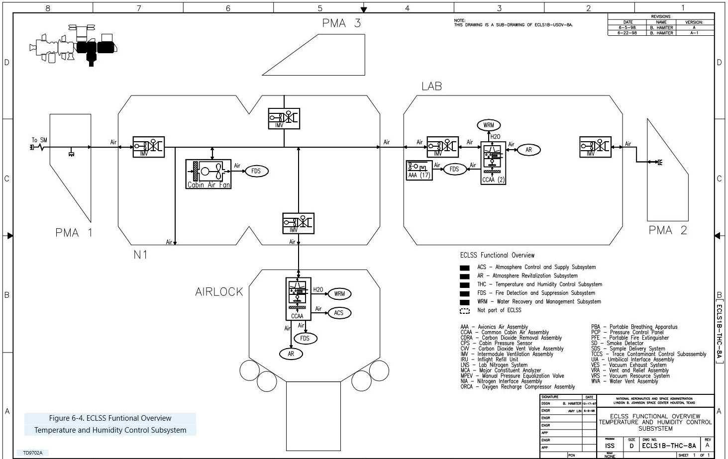
6.3.3.1 Rack Ventilation
The Avionics Air Assembly is used to cool and circulate air
within a specific rack volume. A
fan and non-condensing heat exchanger provide cooling for rack equipment and
circulation for operation of the Fire Detection and Suppression Subsystem Smoke
Detectors. This heat exchanger
interfaces with the Internal Thermal Control System Moderate Temperature Loop.
6.3.3.2 Intramodule
Ventilation
The Common Cabin Air Assembly (CCAA) contains a fan and
condensing heat exchanger to provide intramodule ventilation, temperature
control, and humidity removal.
Before the air enters the CCAA, it is drawn through the High Efficiency
Particulate Air (HEPA) filters which remove particles and bacteria from the
airstream. Moisture in the Station
atmosphere is condensed by the heat exchanger and is sent to the Water Recovery
and Management Subsystem. The heat exchanger interfaces with the Internal
Thermal Control System Low Temperature Loop. Air that has been cooled and
dehumidified is sent to the Atmosphere Revitalization Subsystem Carbon Dioxide
Removal Assembly (CDRA) for its effective operation.
There are two CCAAs in the U.S. Lab, of which only one is normally in
operation at Flight 8A. There is
also a CCAA in the Airlock which is only used during EVA operations.
The Cabin Air Fan in Node 1 provides intramodule circulation but has no
cooling or humidity removal capability.
6.3.3.3 Intermodule
Ventilation
The Intermodule Ventilation (IMV) Assembly is a series of
fans and valves that circulate air between modules through a ducting system.
Hard plumbed ducts are located in most endcones on the USOS, and the
hatches themselves can also act as circulation paths.
The ROS relies on drag-through flexible ducting and open hatches for
intermodule ventilation.
6.3.3.4
Additional Temperature and Humidity Control Capabilities at
Assembly Complete
At Assembly Complete, additional Common Cabin Air
Assemblies (CCAAs) will be available and Intermodule Ventilation (IMV) equipment
will be included in all new modules.
Additional Avionics Air Assemblies will be manifested as required to
support rack equipment.
6.3.4 Fire Detection and
Suppression
Figure
6-5 shows the USOS Fire Detection and Suppression Subsystem and its
interfaces. The Fire Detection and
Suppression Subsystem provides smoke detectors for the Station volumes, fire
extinguishers, portable breathing equipment, and a system of alarms and
automatic software responses for a fire event.
Following a fire, the Atmosphere Revitalization and Temperature and
Humidity Control Subsystems work together to remove contaminants from the
affected volume. In an extreme
situation, the Atmosphere Control and Supply equipment may be used to
depressurize a module to extinguish the fire and/or exhaust the contaminants.
Figure 6-5, ECLSS
Functional Overview Fire Detection and Suppression Subsystem
6.3.4.1 Smoke Detection
In the USOS, the Fire Detection and Suppression Subsystem
provides two area Smoke Detectors in each pressurized module, and a Smoke
Detector in each rack requiring an Avionics Air Assembly.
These Smoke Detectors operate on a light obscuration principle, and are
mounted in Temperature and Humidity Control Subsystem air paths.
The ROS has two types of Smoke Detectors.
One type is similar to USOS Smoke Detectors, and the other is an
ionization type.
A Caution and Warning (C&W) Panel mounted in each USOS
module features lighted emergency buttons.
If smoke is detected, flight software will light the “FIRE” button, sound
an alarm, and shut off Temperature and Humidity Control equipment in the area to
minimize oxygen being fed to the fire.
Crewmembers may also sound (or silence) a fire alarm by manually pushing
the button on the C&W Panel or on the Portable Computer System (PCS).
Fires on the USOS can be extinguished with handheld
Portable Fire Extinguishers, which are filled with carbon dioxide.
These function very similarly to typical fire extinguishers here on
Earth. Two different nozzles allow
the Portable Fire Extinguisher to be used on both open area and rack fires.
The ROS uses fire extinguishers filled with a non-toxic nitrogen based
substance that can be dispensed as a foam or a liquid.
6.3.4.4 Supplemental Oxygen
Supply
During a fire, crewmembers must wear a Portable Breathing
Apparatus (PBA), which is essentially a gas mask and an oxygen bottle.
The PBA can also be plugged into oxygen ports provided by the Atmosphere
Control and Supply Subsystem. The
PBA is particularly important for a crewmember using the Portable Fire
Extinguisher, because carbon dioxide displaces oxygen in the vicinity.
This high concentration of carbon dioxide could cause the crewmember to
lose consciousness if he or she is not supplied direct oxygen through a PBA.
6.3.4.5 Additional Fire
Detection and Suppression Capabilities at Assembly Complete
There are no functional differences between 8A and Assembly
Complete; there will simply be more equipment available.
6.3.5 Water Recovery and
Management
In Figure 6-6,
the USOS Water Recovery and Management Subsystem and its interfaces are
illustrated for a Flight 8A configuration.
This subsystem collects, stores, and distributes the Station's water
resources. The water collected
includes condensate from the Temperature and Humidity Control Subsystem and
return water from EVA activities.
At 8A, collected water is transported to the ROS for processing or is vented
overboard.
Figure 6-6, ECLSS Functional
Overview Water Recovery and Management Subsystem
6.3.5.1 ROS Water Recovery
and Management Overview
The ROS has primary responsibility for water recovery and
management functions for most of the assembly stages of the Station.
The ROS collects condensate water from its condensing heat exchangers and
receives water that is manually transported from the USOS.
It is then purified and monitored for quality.
If water is needed in the Elektron oxygen generator, potable water must
be repurified to remove minerals.
Small tanks are used to store and transport water in various locations on the
ROS. Larger tanks with a pump
assembly, called Rodniks, store potable water both on the exterior of the
Service Module and on Progress modules.
Solid waste products from various sources are collected and put on a
Progress module for incineration upon atmosphere re-entry.
6.3.5.2 USOS Water Recovery and Management
At Flight 8A, the USOS collects condensate water from the
Temperature and Humidity Control Subsystem and waste water from the
Extravehicular Mobility Units (space suits).
Waste water lines transport the water throughout the USOS, and the water
is stored in a tank until it is removed from the system by overboard venting or
manual transport to the ROS.
6.3.5.3 Additional Water
Recovery and Management Capabilities at Assembly Complete
At Assembly Complete, the USOS Water Recovery and
Management Subsystem has several more capabilities.
A network of pipes and another tank will be used to transport and store
water produced by the Shuttle’s fuel cells for use as make-up water on the ISS.
A Urine Processor will separate water from urine and refine it to waste
water. A Potable Water Processor
will then refine waste water (including condensate, fuel cell water, EVA waste
water, and Urine Processor output water) into potable water.
In Figure 6-7,
the interfaces that ECLSS shares with other ISS systems at Flight 8A are
illustrated. At Assembly Complete,
the USOS will also provide potable water to Crew Systems and to EVA Systems.
Figure
6-7. ECLSS interfaces at Flight 8A
There are several important milestones in the buildup of
ISS ECLSS. Because ECLSS is
primarily concerned with the maintenance of living conditions, these milestones
correspond to the arrival of pressurized modules.
6.5.1 Flight 1A/R -
Functional Cargo Block
The Functional Cargo Block (FGB) is the foundation module
of the ISS. It contains the first
few pieces of ECLSS equipment, including circulation fans and non-condensing
atmospheric heat exchangers, fire detection and suppression equipment, and a Gas
Analyzer.
At Flight 2A, Node 1 and two Pressurized Mating Adapters
(PMAs) are delivered to the Station. Node 1 contains a Cabin Air Fan,
Intermodule Ventilation equipment, a Cabin Pressure Sensor, Fire Detection and
Suppression equipment, and Manual Pressure Equalization Valves on each hatch.
6.5.3 Flight 1R - Service
Module
Most of the Russian ECLSS equipment on the Station at
Flight 8A is housed in the Service Module.
This includes the Elektron for oxygen generation, Vozdukh and lithium
hydroxidebased canisters for carbon dioxide removal, a Trace Contaminant Control
Unit and Harmful Impurities Filter for contaminant removal, Gas Analyzers for
major constituent monitoring, fire detection and suppression equipment, air
cooling and humidity removal equipment, urinal and commode facilities, and a
condensate water processor. The
arrival of the Service Module marks the beginning of the three-person permanent
presence capability.
Much of the USOS ECLSS equipment available during most of
the assembly stages arrives with the Lab.
Atmosphere Control and Supply equipment includes gas lines, Pressure
Control Assembly, and Manual Pressure Equalization Valves.
A complete rack of Atmosphere Revitalization equipment arrives, which
contains the Major Constituent Analyzer, Carbon Dioxide Removal Assembly, and
Trace Contaminant Control Subassembly.
The Sample Delivery System lines launched in the Lab and Node 1 are
connected to the Major Constituent Analyzer.
Temperature and Humidity Control equipment includes two Common Cabin Air
Assemblies and more Intermodule Ventilation equipment, as well as Avionics Air
Assemblies in several racks. Fire
Detection and Suppression equipment is launched with the Lab, as are the Water
Recovery and Management condensate tank, Water Vent Assembly, and waste and
(unused) fuel cell water lines.
At Flight 7A, the Airlock is installed, along with much of
the Atmosphere Control and Supply storage and distribution equipment, more
Manual Pressure Equalization Valves, and another Pressure Control Assembly.
Another Common Cabin Air Assembly and more Intermodule Ventilation
equipment arrive, and Sample Delivery System lines are connected to the USOS
network. The standard Fire
Detection and Suppression equipment is manifested, as is the Depressurization
Pump. This flight marks the last
major USOS ECLSS build-up until the arrival of Node 2.
6.6.1 ECLSS Purpose and
Functions
The Environmental Control and Life Support System (ECLSS)
maintains a pressurized habitable environment, provides water recovery and
storage, and provides fire detection and suppression within the ISS.
6.6.2 Subsystem Names and
Functions
There are five major subsystems within ECLSS:
· The Atmosphere Control and Supply Subsystem provides
oxygen and nitrogen to maintain the Station atmosphere at the correct pressure
and composition for human habitation. It also provides gas support to various
users on the Station, and pressure equalization and depressurization
capabilities
· The Atmosphere Revitalization Subsystem ensures that the
atmosphere provided by the Atmosphere Control and Supply Subsystem remains safe
and pleasant to breathe. It
performs carbon dioxide removal, trace contaminant control, and major
atmospheric constituent monitoring
· The Temperature and Humidity Control Subsystem helps
maintain a habitable environment by circulating air, removing humidity and
particulates, and maintaining the temperature of the Station atmosphere.
Three levels of circulation are provided:
rack, intramodule, and intermodule ventilation
· The Fire Detection and Suppression Subsystem provides
smoke detection sensors for the Station volumes, fire extinguishers, portable
breathing equipment, and a system of alarms and automatic software actions to
annunciate and automatically respond to a fire event
· The Water Recovery and Management Subsystem collects,
stores, and distributes the Station's water resources.
Figure 6-8 shows how all the
components of the subsystems interact with each other.
There are three major milestones in the buildup of USOS
ECLSS capabilities. On Flight 2A,
Node 1 contains the first pieces of USOS ECLSS equipment, consisting principally
of ventilation and Fire Detection and Suppression equipment.
Next, on Flight 5A, the Lab module carries a majority of the U.S. ECLSS
equipment discussed in this manual, including major portions of all subsystems.
Finally, on Flight 7A in the Airlock, the full capabilities of Atmosphere
Control and Supply are enabled, and additional Temperature and Humidity Control
and Fire Detection and Suppression equipment ensures crew health and comfort
during EVA operations.