Apollo Guide
Apollo 11 Landing Site

Central Station
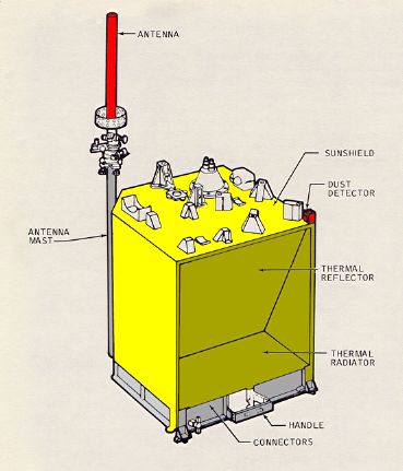
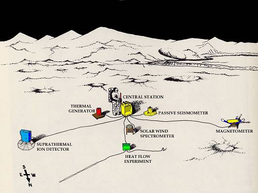
The ALSEP system, first flown on the Apollo 12 mission, consisted of a Central Station with an communications package and with leads running out to the instruments placed around it. DC power of 70 watts at 16 volts was supplied by a SNAP-27 model radioisotope thermo-electric generator (RTG), placed beside the station and connected to it by cables. A radioactive, plutonium fuel element for the generator was carried to the Moon in a protective cask mounted on the side of the Lunar Module, and was removed and inserted in the generator by the astronauts after they offloaded the generator and placed it on the ground. The power required by the whole station and experiments was less than the power of a medidem powered light bulb.
The station and instruments had to be deployed at a distance of at least 90 meters west from the LM to minimise disturbance from the LM lift-off. ALSEP deployment, power-up, and activation was planned to take a maximum of 120 minutes. The instruments were arrayed around the central station, which supplied power to run the instruments and provided two-way communications so data collected by the experiments could be relayed to Earth and commands could be received. The central station was a 25-kilogram box with thermal control achieved by passive elements (insulation, reflectors, thermal coatings) as well as power dissipation resistors and heaters. Communications with Earth was with transmitters, receivers, data processors and multiplexers housed within the central station, with signals transmitted through a 58 centimeter by 3.8 centimeter modified axial-helical antenna mounted on top, and pointed towards Earth by the astronauts. Data collected from the instruments was converted into a telemetry format and transmitted to Earth. The ALSEP systems and instruments were controlled by commands from Earth, sent through the tracking stations.
The uplink frequency for all Apollo ALSEP's was 2119.0 MHz.
The down link frequencies were:
Non - Normal
An unexpected problem with the first ALSEP on Apollo 12 involved the cables that connected the various experiment modules to the Central Station. Although the cables were fairly stiff, on Earth they tended to lie flat to the ground, held down by their own weight. However, on the Moon, the cables hardly seemed to notice the one sixth gravity and retained loops and bends they had acquired during storage inside the LM - loops that stood up from the ground rather like sections of a frozen garden hose. There were no disastrous tripping episodes during Apollo 12 such as occurred on Apollo 16, but the need to dodge cable loops slowed the astronaut's work.
 |
 |
|
|
|
Home / Acronyms / Index / Schematics / Systems
Operations / Non-Normal / Normal
Panels / 1 / 2 / 3 / 4 / 5 / 6 / 8 / 12 /14
Copyright 2024 APOLLO 11 GUIDE©