APOLLO
11 OPERATIONS HANDBOOK BLOCK II SPACECRAFT
Spacesuit Assembly
(Intravehicular)
Bioinstrumentation
Harness and Biomed Belt
Shirtsleeve
Environment lntravehicular Apparel
Urine Collection
and Transfer Assembly and UCO Clamps
Communication
Soft Hat, Lightweight Headset, and Eartube
Constant Wear
Garment (CWG) "T" Adapter
Communications
Cable With Control Head
Pressure Garment
Assembly (PGA)
Intravehicular
Spacesuit Diagram
PGA and Helmet
Stowage Bags Diagram
Miscellaneous
Personal Equipment
Oxygen Hose
Assembly and Accessories Diagram
Extravehicular
Mobility Unit (EMU)
Crewman
Restraint Harness Subsystem With Heel Restraints
Restraint Harness
Buckle Stowage Straps
Diagram
Handholds, Hand
Straps and Hand Bar Diagram
Guidance and Navigation Station Restraint
Sleep Station
Restraints Diagram
Center Couch
Restraint Straps Diagram
Probe and Drogue
Stowage Straps Diagram
Velcro and Snaps
Retainer Locations
Sleep Restraint Tie
down Ropes
SIGHTING AND
ILLUMINATION AIDS
Internal Sighting
and Illumination Aids
Internal
Sighting and Illumination Aids Diagram
Window Shades and
Mirrors Diagram
Crewman Optical
Alignment Sight (COAS)
Crewman
Optical Alignment Sight System Diagram
LM Active Docking
Target Diagram
Center (Hatch)
Window Frame Markings
Right Rendezvous
Window Frame Markings
Miscellaneous
Internal Sighting and Illumination Aids Diagram
Miscellaneous
Internal Sighting and Illumination Aids Diagram
Meter Covers
(Altimeter and Accelerometer)
External Sighting
and Illumination Aids
External
Illumination Aids Diagram
EVA Handles With RL
Disks Diagram
Mission Operational
Aids Diagram
CREW PERSONAL
EQUIPMENT Diagram
Tools 3 and 4
Number 8 and 10 Torque Set Drivers
16 mm Data
Acquisition Camera Diagram
Data Acquisition
Camera Bracket
70 mm Hasselblad
Electric Camera and Accessories
70
mm Hasselblad Electric Camera and Accessories Diagram
Lunar Surface 70 mm
Film Magazine
70 mm Magazine LM
Transfer Bag
70 mm Camera Mount
for 80 and 250 mm Lens
70 mm Camera Mount
for 500 mm Lens
Accessories and
Miscellaneous Equipment
Accessory
and Miscellaneous Equipment Diagram Sheet 1
Accessories and
Miscellaneous Equipment Diagram 3
Accessory and
Miscellaneous Equipment Diagram Sheet 2
Voice Recorder,
Cassettes, and Battery Packs
Accessories and
Miscellaneous Equipment Decontamination Equipment Diagram
Vacuum Cleaning
Hose and Brushes
Utility
and Scientific Electrical Outlet Diagram
Scientific
Instrumentation Outlets
Drinking Water
Subsystem Diagram
Food Preparation
Water System Diagram
Waste Management
System and Supplies
Waste Management
System Diagram
Urine Subsystem
Components Diagram
Gemini Urine
Transfer System (UTS)
Urinating Using the
Urine Receptacle Assembly
Draining the UCTA
While in the Spacesuit
Draining the UCTA
After Removal From Spacesuit
Auxiliary Dump
Nozzle Operations Diagram
Waste Stowage Vent
System Diagram
Personal Hygiene
Items Diagram
Oral Hygiene Set -
Cleansing of Teeth
MEDICAL SUPPLIES
AND EQUIPMENT
Bioinstrumentation
Harness Diagram
Personal Biomedical
Sensors Instrument Assembly
Biomedical Signal
Conditioner Assembly
Bioinstrumentation
Accessories or Spares
Medical Accessories
Kit Diagram
RADIATION
MONITORING AND MEASURING EQUIPMENT
Radiation
Monitoring and Measuring Equipment Diagram
Personal Radiation
Dosimeter (PRD)
Van Allen Belt
Dosimeter (VABD)
Nuclear Particle
Detection System (NPDS)
Postlanding
Ventilation (PLV) Ducts
Postlanding
Ventilation Ducts Diagram
Swimmer Umbilical
and Dye Marker
Swimmer Umbilical
and Dye Marker Diagram
This section contains the description and operation of
Contractor and NASA- furnished crew personal equipment and miscellaneous
stowed equipment that is not described in other sections of the handbook.
All major items are identified as Contractor-furnished equipment (CFE) or
Government-furnished (NASA) property (GFP - synonymous with GFE).
The crew equipment will be presented in the general
order of operational usage. A brief outline is as follows:
A.
Spacesuits
1.
Intravehicular Spacesuit Assembly
(a)
Biomedical
Harness and Belt
(b)
Constant
Wear Garment (CWG)
(c)
Flight
Coveralls
(d)
Pressure
Garment Assembly (PGA)
(e)
Associated Umbilicals, Adapters , and Equipment
2.
Extravehicular Spacesuit Assembly
(a)
Liquid-Cooled
Garment (LCG)
(b)
PGA
with Integrated Thermal Meteroid Garment (ITMG)
2.
Interior
Handhold and Straps
3.
Hand Bar
C.
Zero-g
Restraints (paragraph 12 .1 2 .3)
2.
Velcro
and Snap Restraint Areas
3.
Straps
D.
Internal Sighting and Illumination Aids (paragraph 2.12.4)
2.
Mirrors
3.
Crewman Optical Alignment Sight (COAS)
E.
External Sighting and Illumination Aids
3.
Cameras
4.
Accessories & Miscellaneous
(a)
Waste
Bags
(b)
Pilot’s
Preference Kits (PPKs)
(d)
Oxygen
Masks
(e)
Utility
Outlets
(f)
Scientific Instrumentation Outlets
1.
Water
2.
Food
H.
Medical
Supplies and Equipment
I.
Radiation Monitoring and Measuring Equipment
1.
Postlanding Ventilation Ducts
2.
Swimmer
Umbilical and Dye Marker
6.
Survival
Kit
On the following pages is an alphabetical listing of
the stowable Apollo crew personal and miscellaneous equipment that will be
described in this section. Miscellaneous spacecraft equipment that is
mounted on spacecraft structure internally or externally is described in
this section but is not listed in the following chart.
|
Item |
CFE |
GFP |
Qty |
Dimensions |
Total Wt (Lb) |
Wt Each (Lb) |
Paragraph |
||
|
L |
W |
H |
|||||||
|
Adapter, CWG electrical, w bag |
|
X |
4 |
|
|
|
|
|
2.12.2 |
|
Adapter, contingency feeding |
|
X |
1 |
|
|
|
|
|
2.16.2 |
|
Adapter, gas sep drying |
|
X |
1 |
1.5” |
|
|
|
|
2.16.2 |
|
Adapter, urine hose to UCTA |
|
X |
1 |
5” |
1”D |
|
|
|
2.16.2 |
|
Bag accessory |
|
X |
3 |
|
|
|
.60 |
.20 |
2.12.5 |
|
Bag, helmet stowage |
|
X |
3 |
|
|
|
.99 |
.33 |
2.12.2 |
|
Bag, PGA stowage |
X |
|
1 |
32” |
18” |
2” |
|
4.3 |
2.12.2 |
|
Bag , gas separator |
X |
|
1 |
7” |
4” |
1.5” |
|
|
2.12.6 |
|
Bags, temp stowage |
X |
|
3 |
36” |
13” |
1” |
5.1 |
1.7 |
2.12.5 |
|
Bag, tunnel hatch |
X |
|
1 |
|
28”D |
|
|
|
2.12.3 |
|
Battery, voice recorder |
|
X |
5 |
2.0” |
1.8” |
0.65” |
|
|
2.12.5 |
|
Bracket, 16mm DAC |
X |
|
1 |
7” |
|
|
0.7 |
0.7 |
2.12.5 |
|
Brush, vac cleaning |
|
X |
2 |
1.63” |
1.8”D |
|
|
|
2.12.5 |
|
Cable, aux dump nozzle htr |
X |
|
1 |
108” |
|
|
|
0.2 |
2.12.6 |
|
Cable, grounding |
X |
|
1 |
|
|
|
|
|
2.12.5 |
|
Camera, 70 mm electric Hasselblad |
|
X |
1 |
5” |
4” |
5” |
|
4.04 |
2.12.5 |
|
Camera, 16 mm data acquisition with power cable |
|
X |
1 |
7” |
4” |
2” |
|
1.93 |
2.12.5 |
|
Cap, hose screen, w bag |
X |
|
3 |
|
|
|
1.00 |
0.20 |
2.12.2 |
|
Cap, gas sep nozzle |
|
X |
1 |
1” |
|
|
|
|
2.12.6 |
|
Cap, aux dump nozzle pressure |
X |
|
1 |
|
|
|
|
0.20 |
2.12.6 |
|
Cassette, 70 mn1 camera film |
|
X |
* |
|
|
|
|
|
|
|
Clamps, UCTA |
|
X |
3 |
|
|
|
0.03 |
0.01 |
2.12.2 |
|
Cloth, dry cleansing |
|
X |
* |
2” |
2” |
|
|
|
2.12.6 |
|
Cloth, wet cleansing |
|
X |
|
2” |
2” |
|
|
|
2.12.6 |
|
Communication cable |
X |
|
2 |
74” |
|
|
7.8 |
3.9 |
2.12.2 |
|
Communication cable w control head, w bag |
X |
|
2 |
121” |
|
|
8.4 |
4.2 |
2.12.2 |
|
Communication carrier (snoopy helmet) |
|
X |
3 |
|
|
|
|
|
2.12.2 |
|
Coupling, oxygen hose w bag |
X |
|
3 |
|
|
|
1.1 |
2.0 |
2.12.2 |
|
Container , decontamination, CU cam cassette |
X |
|
1 |
|
|
|
|
|
2.12.5 |
|
Container, decontamination, LSR |
X |
|
1 |
|
|
|
|
|
2.12.5 |
|
Container, decontamination, LSR (rock box),
large |
X |
|
1 |
|
|
|
|
|
2.12.5 |
|
Container, decontamination, 70 mm Hblad mag |
X |
|
1 |
|
|
|
|
|
2.12.5 |
|
Container, Frozen Food |
X |
|
1 |
|
|
|
|
|
2.12.6 |
|
Cover, meter |
|
X |
2 |
|
3”D |
|
|
|
2.12.4 |
|
Cover, PGA elec conn protective |
|
X |
3 |
|
|
|
|
|
2.12.3 |
|
Coveralls, inflight |
|
X |
3 |
|
|
|
9.7 |
3.2 |
2.12.2 |
|
Diaphragm, w cover |
X |
|
3 |
3” |
3”D |
|
|
|
2.12.6 |
|
Dishes |
X |
|
3 |
6” |
5” |
|
|
|
2.12.6 |
|
Docking target, LM active |
X |
|
1 |
8” |
8” |
|
|
1.8 |
2.12.4 |
|
Dosimeters, passive |
|
X |
9 |
|
|
|
0.18 |
0.02 |
2.12.8 |
|
Dosimeters, personal |
|
X |
3 |
|
|
|
1.14 |
0.38 |
2.12.8 |
|
Ducts, postlanding ventilation (PLV) w bag |
X |
|
3 |
|
|
|
0.60 |
0.10 |
2.12.9 |
|
Eartube, universal |
|
X |
3 |
|
|
|
0.03 |
0.01 |
2.12.2 |
|
Exerciser, inflight |
|
X |
1 |
|
|
|
|
1.22 |
2.12.5 |
|
Eyepatch |
|
X |
1 |
|
|
|
|
|
2.12.4 |
|
Fecal collection assy |
X |
|
30 |
8” |
3” |
1” |
4.20 |
0.14 |
2.12.4 |
|
Fecal containment system |
|
X |
3 |
|
|
|
1.50 |
0.50 |
2.12.2 |
|
Filter , red (Hblad cam) |
|
X |
1 |
|
|
|
|
0.05 |
2.12.5 |
|
Filter, high density, sun |
|
X |
2 |
|
|
|
2.8 |
1.4 |
2.12.4 |
|
Filter , Photar (HEC cam) |
|
X |
1 |
|
|
|
|
0.05 |
2.12.5 |
|
Filter , QD gas & liq |
X |
|
2 |
|
|
|
1.0 |
0.5 |
2.12.6 |
|
Fire extinguisher |
X |
|
1 |
8.5” |
5”D |
|
|
7.5 |
2.12.5 |
|
Flight data file with locker R12 |
X |
X |
* |
|
|
|
|
20.0 |
2.12.5 |
|
Food set |
|
X |
1 |
|
|
|
|
40.0 |
2.12.6 |
|
Food set, w hygiene items |
|
X |
1 |
|
|
|
|
30.8 |
2.12.6 |
|
Food warmer |
X |
|
1 |
10 |
6 |
7 |
|
|
2.12.6 |
|
Garment, constant wear (CWG) |
|
X |
6 |
Folded 12” |
6” |
2” |
5.6 |
0.8 |
2.12.2 |
|
Garment, liquid cooled |
|
X |
2 |
|
|
|
8.18 |
4.13 |
2.12.2 |
|
Glareshade, MDC |
X |
|
3 |
|
|
|
|
|
2.12.4 |
|
Glareshield, floodlight w bag |
|
X |
2 |
|
|
|
|
|
2.12.4 |
|
Gloves, IV (pr) |
|
X |
1 |
|
|
|
|
|
2.12.2 |
|
Handholds |
X |
|
2 |
|
|
|
|
|
2.12.3 |
|
Handbar |
X |
|
1 |
|
|
|
|
|
2.12.3 |
|
Hand straps |
X |
|
8 |
|
|
|
|
|
2.12.3 |
|
Harness, crewman restraint |
X |
|
3 |
|
|
|
|
|
2.12.3 |
|
Harness assy, bioinstrumentation |
|
X |
3 |
|
|
|
3.3 |
1.1 |
2.12.7 |
|
Headrest, pad |
|
X |
3 |
|
|
|
3.0 |
1.0 |
2.12.5 |
|
Headset, lightweight |
|
X |
3 |
|
|
|
0.9 |
0.3 |
2.12.2 |
|
Heel restraint, pr |
|
X |
3 |
4” |
3.5 |
1.0” |
3.3 |
1.0 |
2.12.5 |
|
Helmet, shield |
|
X |
1 |
|
|
|
|
0.79 |
2.12.2 |
|
Hook, line snagging w bag |
X |
|
1 |
|
|
|
1.7 |
1.9 |
2.12.9 |
|
Hose, vac cleaning |
X |
|
1 |
41.5” |
|
|
|
|
2.12.5 |
|
Hose assy, oxygen |
X |
|
2 |
72” |
|
|
10.6 |
5.3 |
2.12.2 |
|
Hot pad |
X |
|
1 |
9” |
4” |
|
|
|
2.12.6 |
|
Hygiene, oral assembly |
|
X |
1 |
|
|
|
1.0 |
0.3 |
2.12.6 |
|
Intervalometer |
|
X |
1 |
|
|
|
|
0.25 |
2.12.5 |
|
Kit, EMU maintenance |
|
X |
1 |
|
|
|
|
0.38 |
2.12.2 |
|
Kit, medical |
|
X |
1 |
7” |
5” |
5” |
|
3.0 |
2.12.7 |
|
Kit, pilot's preference |
|
X |
3 |
|
|
|
1.5 |
0.5 |
2.12.5 |
|
Lens , 5 mm ( 16 mm camera (with cover) |
|
X |
1 |
|
|
|
|
0.68 |
2.12.5 |
|
Lens , 18 mm ( 16 mm camera) |
|
X |
1 |
|
|
|
|
0.56 |
2.12.5 |
|
Lens , 18 mm Kern (16 mm cam |
|
X |
1 |
|
|
|
|
0.48 |
2.12.5 |
|
Lens, 75 mm (16 mm camera) |
|
X |
1 |
|
|
|
|
0.53 |
2.12.5 |
|
Lens, 75 mm Kern (16 mm cam) |
|
X |
1 |
|
|
|
|
0.50 |
2.12.5 |
|
Lens, 250 mm (70 mm Hasselblad) |
|
X |
1 |
6.2” |
3.1” |
3.1” |
|
2.10 |
2.12.5 |
|
Lens, 500 mm (70 mm (Hblad) |
|
X |
1 |
12.5” |
3.5” |
|
|
|
2.12.5 |
|
Life vest |
|
X |
3 |
|
|
|
7.5 |
2.5 |
2.12.2 |
|
Magazines, 70 mm camera film |
|
X |
* |
3.82” |
3.6” |
1.86” |
|
0.76 |
2.12.5 |
|
Magazines, lunar surface Hasselblad |
|
X |
1 |
|
|
|
|
1.75 |
2.12.5 |
|
Magazines, 16 mm OAC |
|
X |
* |
|
|
|
|
0.97 |
2.12.5 |
|
Masks, oxygen whose |
|
X |
3 |
|
|
|
3.60 |
1.30 |
2.12.5 |
|
Meter, radiation survey |
|
X |
1 |
|
|
|
|
1.60 |
2.12.8 |
|
Mirror assy, internal
viewing |
X |
|
3 |
4.25 |
3.5 |
|
|
|
2.12.4 |
|
Mirror, 16 mm camera right angle |
|
X |
1 |
|
|
|
|
0.16 |
2.12.5 |
|
Monocular |
|
X |
1 |
|
|
|
|
0.75 |
2.12.4 |
|
Mount, 70 mm Hblad |
|
X |
1 |
9” |
|
|
|
|
2.12.5 |
|
Pencil |
|
X |
3 |
|
|
|
0.15 |
0.05 |
2.12.2 |
|
Penlights |
|
X |
6 |
7” |
1.5” |
|
2.04 |
0.34 |
2.12.2 |
|
Pen, marker |
|
X |
3 |
|
|
|
0.15 |
0.05 |
2.12.2 |
|
Pens, data recording |
|
X |
3 |
|
|
|
0.15 |
0.05 |
2.12.2 |
|
Pouch, food retainer |
|
X |
2 |
|
|
|
|
|
2.12.6 |
|
Pump, sea water |
X |
|
1 |
|
|
|
|
1.60 |
2.12.9 |
|
QD, aux dump nozzle |
X |
|
1 |
4” |
1”D |
|
|
0.20 |
2.12.6 |
|
QD, water (waste) panel |
X |
|
1 |
4.5” |
1”D |
|
|
0.30 |
2.12.6 |
|
Restraint, sleep station |
X |
|
3 |
|
|
|
10.8 |
3.60 |
2.12.3 |
|
Ring sight |
|
X |
1 |
1.26” |
1.2” |
0.64” |
0.08 |
|
2.12.5 |
|
Rollon cuff assembly |
|
X |
3 |
|
|
|
|
|
2.12.6 |
|
Ropes, sleep restraint tiedown |
X |
|
5 |
10’ |
0.3”D |
|
3.5 |
0.7 |
2.12.3 |
|
Scissors (large) |
|
X |
3 |
8” |
2” |
|
1.62 |
0.53 |
2.12.2 |
|
Separator, gas |
|
X |
2 |
6” |
|
|
|
|
2.12.6 |
|
Shades, rendezvous window |
X |
|
2 |
13” |
8” |
|
0.24 |
0.12 |
2.12.4 |
|
Shade, side hatch |
X |
|
1 |
|
10”D |
|
|
1.4 |
2.12.4 |
|
Shades, side viewing window |
X |
|
2 |
13” |
13” |
|
3.4 |
1.7 |
2.12.4 |
|
Sight, crew optical alignment (COAS) w filter |
X |
|
1 |
8” |
2”D |
|
|
1.5 |
2.12.4 |
|
Spacesuit, intravehicular |
|
X |
1 |
|
|
|
|
35.61 |
2.12.2 |
|
Spacesuit, extravehicular |
|
X |
2 |
|
|
|
94.72 |
47.36 |
2.12.2 |
|
Spotmeter, automatic |
|
X |
1 |
7” |
4” |
|
|
.94 |
2.12.5 |
|
Straps, utility |
X |
|
13 |
12” |
|
|
0.39 |
0.03 |
2.12.3 |
|
Strap, center couch DPS burn |
X |
|
1 |
|
|
|
|
0.2 |
2.12.3 |
|
Straps, center couch stow |
X |
|
2 |
|
|
|
|
|
2.12.3 |
|
Straps, control cable |
X |
|
4 |
11” |
|
|
|
|
2.12.3 |
|
Straps, drogue stow |
X |
|
3 |
|
|
|
|
|
2.12.3 |
|
Straps, glareshade |
X |
|
4 |
5.5” |
|
|
|
|
2.12.3 |
|
Straps, probe stowage |
X |
|
2 |
|
|
|
|
|
2.12.3 |
|
Straps, cable routing |
X |
|
3 |
5.5” |
|
|
|
|
2.12.3 |
|
Sunglasses with pouch |
|
X |
3 |
|
|
|
0.06 |
0.02 |
2.12.2 |
|
Survival rucksack 1 |
|
X |
1 |
18.0” |
6.0” |
6.0” |
|
34.9 |
2.12.9 |
|
Survival rucksack 2 |
|
X |
1 |
18.0” |
6.0” |
6.0” |
|
34.9 |
2.12.9 |
|
Tape cassette, voice recorder |
|
X |
5 |
3.9” |
25” |
0.4” |
0.5 |
0.1 |
2.12.5 |
|
Tape ( roll) |
|
X |
1 |
6”D |
|
|
|
.88 |
2.12.5 |
|
Timer, two speed |
|
X |
1 |
|
|
|
0.4 |
0.4 |
2.12.5 |
|
Tissue dispensers |
|
X |
7 |
8” |
4” |
3” |
0.39 |
1.42 |
2.12.6 |
|
Toolset, inflight |
X |
|
1 |
|
|
|
|
4.6 |
2.12.5 |
|
Towels, utility (pack) |
|
X |
3 |
|
|
|
2.49 |
0.83 |
2.12.6 |
|
Urine collection & transfer assembly |
|
X |
3 |
|
|
|
1.29 |
0.43 |
2.12.2 |
|
Urine hose |
|
X |
1 |
120” |
1”D |
|
1.30 |
1.30 |
2.12.6 |
|
Urine transfer system (Gemini) |
|
X |
3 |
12” |
9” |
1” |
|
1.3 |
2.12.6 |
|
Uri ne receptacle assy |
X |
|
1 |
|
|
|
|
|
2.12.6 |
|
Vacuum brush |
|
X |
2 |
|
|
1.63” |
|
|
2.12.5 |
|
Vacuum hose |
X |
|
1 |
39” |
|
|
|
|
2.12.5 |
|
Vacuum QD (cabin vent) |
X |
|
1 |
5” |
1.5”D |
|
|
|
2.12.6 |
|
Voice recorder |
|
X |
1 |
5.3” |
|
|
1.2 |
1.2 |
2.12.5 |
|
Watch with watchband |
|
X |
3 |
|
|
|
0.45 |
0.15 |
2.12.2 |
|
Water metering dispenser |
|
X |
1 |
9” |
|
|
|
1.5 |
2.12.6 |
A spacesuit is an enclosed unit that provides a crewman
with a life supporting atmosphere and protective apparel in a space
environment. It will be considered in two conditions: intra vehicular and
extravehicular.
In the intravehicular condition, the apparel is called
the intravehicular spacesuit and consists of the bioinstrumentation
harness assembly, a constant wear garment (CWG), a pressure garment
assembly (PGA) with intravehicular cover (IC), and associated equipment
(contained on or within the spacesuit). The adapters and umbilical hoses
that connect the space suit to the spacecraft systems are also described
in this subsection.
In the extravehicular condition, the apparel is called
the extravehicular mobility unit (EMU) and consists of a fecal containment
system, a urine collection and transfer assembly (UCTA), the
bioinstrumentation harness assembly, a liquid-cooled garment (LCG),
communications soft hat, an extravehicular spacesuit, a portable life
support system (PLSS), oxygen purge system (OPS), integrated thermal
micrometeoroid garment (ITMG), an extravehicular visor assembly (EV
visor), and associated equipment contained on or within the E MU. The PLSS
and OPS will not be described in this handbook.
Spacesuit Assembly (Intravehicular)
The intra vehicular spacesuit is depicted in Spacesuits Diagram. The
intravehicular condition has two subconditions, unsuited and suited. In
the unsuited condition or "shirtsleeve environment, " the crewman breathes
the oxygen in the spacecraft cabin and wears a bioinstrumentation harness,
a communication soft hat for communication, a constant wear garment (CWG)
for comfort, flight coveralls for warmth, and booties for zero-g
restraint. A CWG adapter is used to connect the communications soft hat
(CSH) and the bioinstrumentation harness signals to the communications
cable. The comm cable attaches to connectors between panel s 300 and 301
to complete the signal flow to the audio center.
In the suited condition, the crewman wears his
bioinstrumentation harness, a communication soft hat, a CWG, a pressure
garment assembly (PGA) with IC, and breathes oxygen within the garment. An
oxygen hose assembly delivers the oxygen to the suit and returns it to the
ECS. The comm cable connects directly to the PGA for telecommunications
signal flow. In this condition there are two ECS modes of operation,
ventilated and pressurized.
Bioinstrumentation
Harness and Biomed Belt
(Shirtsleeve
Environment lntravehicular Apparel).
Shirtsleeve
Environment lntravehicular Apparel
The purpose of the bioinstrumentation harness is to
furnish the biomedical signals to monitor the crews’ physical condition,
and consists of sensors, signal conditioners, a biomed belt, and wire
signal carriers. For a complete description, refer to
Medical Supplies and Equipment.
Each crewman will have sensors attached to his skin for
the entire mission. These sensors have wire leads encased in plastic with
a small connector at the other end. The connectors are inserted through
the CWG and connected to the signal conditioners in the biomed belt. The
biomed belt is cloth, has four pockets, and snaps in the corners to attach
to the CWG.
There are three signal conditioners: one for ECG, one
for the impedance pneumograph (ZP), and one dc-dc converter which fits
into pockets on the biomed belt, located around the abdomen. The signal
conditioners are interconnected by a wire harness which has a 9-socket
connector.
The fecal containment system (FCS) is a chemically
treated under pant worn under the LCG during periods of extravehicular
activity (EVA). In the event of an uncontrolled bowel movement, the
chemicals in the underpant will neutralize the feces. At launch and entry,
the fecal containment systems are stowed. Spacesuits Diagram
Urine Collection and Transfer Assembly and UCO Clamps
The urine collection and transfer assembly (UCTA)
functions to transfer the urine from the suited crewman to the suit during
emergency urinations
Spacesuits Diagram. This condition could occur during a "hold"
on the launch pad or EVA.
The UCTA consists of a belt, shaped bladder, roll-on
(external catheter), and a tube leading to the spacesuit urine collection
QD.
The UCTA is donned over the fecal containment system.
When doffing the UCTA, the_ UCD clamps are used to seal urine in the tube
to prevent leakage into the crew compartment. The urine in the UCTA can be
drained while it is in the spacesuit or after it is removed. For the
procedure, refer to section
2.12.6.
Constant Wear Garment (CWG) (Shirtsleeve Environment lntravehicular Apparel)
The constant wear garment (CWG) is used as an
undergarment for the PGA and provides warmth for the crewman while
unsuited in the shirtsleeve environment. As an additional purpose, this
garment provides an attach point for the biomed belt.
The CWG is a porous cloth, one-piece garment similar to
long underwear. It has a zipper from the waist to the neck for donning and
doffing. An opening in front is for urination and one in the rear for
defecation, without CWG removal. There are snaps at the mid-section to I
attach the biomed belt with signal conditioners, and pockets for film
packet passive dosimeters at the ankles, thighs, and chest. It also has
integral socks.
The CWG can be worn for 6 to 7 days before a change is
required. Three CWGs will be worn aboard by the crew with three being
stowed in a locker, allowing one CWG change each.
Flight Coveralls (Shirtsleeve Environment lntravehicular Apparel)
The flight coveralls help keep the CWG clean, provide
additional crewman warmth,· and provide stowage for miscellaneous personal
equipment while in a shirtsleeve environment. It is a two-piece garment
and 1s stowed at launch and entry. Accessories include a pair of booties
with Velcro patches on the soles for restraint.
Communication Soft Hat, Lightweight Headset, and Eartube (Shirtsleeve Environment lntravehicular Apparel)
The communication soft hat is worn at all times, in or
out of the PGA, for the purpose of communications. Alternate names for it
is communications carrier (comm carrier) or "Snoopy" helmet.
The comm soft hat has two earphones and two
microphones, with voice tubes on two mounts that fit over the ears. The
hat or helmet is cloth and has lacing to adjust the fit to the individual
crewman. A chin strap secures the hat to the head. A small pocket on the
inside near the right temple will hold a passive dosimeter film packet. An
electrical cable with a 21-socket connector will connect to the CWG
adapter or PGA.
The lightweight headset is a single microphone and
earpiece held on the head by a head band. It can be used in place of the
comm carrier while in a shirtsleeve environment.
The universal ear tube attaches to the lightweight
headset earphone. The ear tube is a short length of plastic tube with an
ear fitting that conducts sound from the earphone to the ear. It is stowed
in a pocket of the in-flight coverall.
Constant Wear Garment (CWG) "T" Adapter (Shirtsleeve Environment lntravehicular Apparel)
Communications and bioinstrumentation signals are
transmitted to the communications cable by the CWG T-Adapter; it is used
when in the shirtsleeve environment.
The CWG T-Adapter has a 6 1-socket connector pull in
the middle, and two pigtails, one with a 9-pin connector and one with a
21-pin connector.
There are three CWG “T” Adapters which are stowed when
not in use plus a spare.
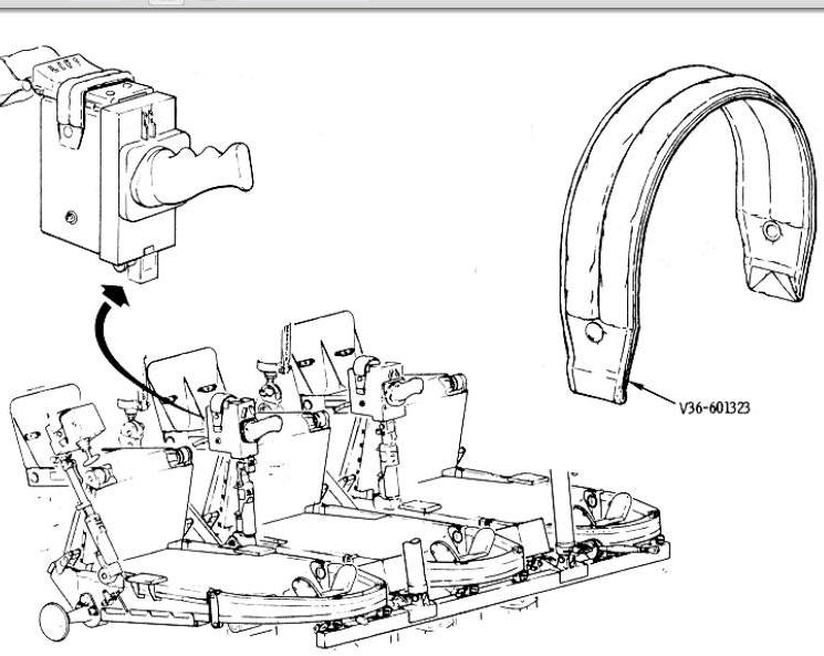
Communications Cable With Control Head
The communications cable, or comm cable, transmits
voice communications and bioinstrumentation signals from the adapters and
crew to the spacecraft bulkhead connectors. It also carries electrical
power and the caution warning (C/W) system audible alarm signal.
The comm cable consists of a control head and a cable.
The control head has a 61-pin connector, a rocker switch and a 37-pin
connector. The cable has a 37-pin connector at one end and a 37-pin
connector with a lanyard pull at the spacecraft bulkhead end. The cables
for the Commander and CM Pilot are 74 inches long. The LM Pilot's cable is
121 inches in length, which allows it to be used for crew transfer through
the tunnel into the LM. One spare control head and cable (121 inches) is
carried in the event of a malfunction.
Pressure Garment Assembly (PGA) (Intravehicular Spacesuit Diagram)
Intravehicular
Spacesuit Diagram
The major component of the spacesuit is the pressure
garment assembly (PGA). The A 7L pressure garment assembly (PGA) provides
a mobile life support chamber that can be pressurized separately from the
cabin inner structure in case of a leak or puncture. The PGA consists of a
helmet, gloves, and torso and limb assembly. It requires an oxygen hose
for oxygen and electrical cable for telecommunications.
The blue torso has a neck ring for securing the helmet
and wrist rings for securing the gloves. It is constructed of Beta cloth
(a fiberglasstype material). A double zipper runs from the crotch area
along the back to the neck ring for donning and doffing. Snaps are located
on the upper chest for securing the life vest. The right wrist area has a
pressure gage with a range of 2 to 5 psia. Two cables run laterally from
the chest, around the biceps, to the spine as an anti-ballooning device,
and are attached and detached at the chest. Two adjustment straps
restraining the neck ring are located in the front (sternal area) and rear
(spinal area).
On the right chest area is a 61 -pin telecommunications
connector. When not in use and during stowage, the connector is protected
by a PGA electrical connector protective cover. The inside
telecommunications harness splits to a 9-pin connector
(bioinstrumentation) and a 21-pin connector (communications). On the left
chest area is a connector for the FLSS liquid system. Inside, it has a
supply hose and a return hose with connectors that connect to the liquid
cooled garment (LCG) when worn in place of the CWG.
Two sets of oxygen hose connectors are located· on the
left- and right-lower rib cage area. A set consists of a blue supply
connector and red return connector. The left connector set is normally for
the PLSS hoses and the right set for the CM ECS hoses, ·but the oxygen
hose connectors will fit either set. To prevent an alien object from
entering and damaging a spacesuit Oz hose connector, a PGA gas connector
plug (Intravehicular
Spacesuit Diagram) is inserted when an O2
connector is not in use. The gas connector plugs are color coded red and
blue to match the O2
connectors. To insert, fit the plug into the connector and press until it
clicks. It mechanically locks in place. To remove, unlock the plug by
pressing the gold lockpin, then lift the locking tabs, rotate the locking
ring, and pull the plug. The intravehicular PGA or spacesuit has only one
set of hose connectors on the right side as there is no extravehicular or
FLSS requirement.
Leg pockets are placed in accordance with the defined
locations. These are used to contain the numerous personal items.
Additional pockets are strapped on the legs to hold other miscellaneous
items. The boots are integral to the torso and the soles have Velcro
patches for restraint. The boot heels have partial steel plates to wedge
in the couch footpan cleats for restraining the feet. The gloves secure to
the wrist ring with a slide lock and rotate by means of a ball bearing
race.
The intravehicular cover (IC) is for added wear
protection of the torso. It is also Beta cloth, with external teflon
patches at maximum wear points. The cover will be laced over the torso and
limbs for operational use and intravehicular (IV) gloves will be worn to
protect the PGA gloves when performing rough handling tasks. The PGA with
the intra vehicular cover is commonly called an intravehicular spacesuit.
The PGA with the integrated thermal micrometeoroid garment (ITMG) is
termed the extravehicular spacesuit. For mission or operational purposes,
the spacesuit includes the PGA and the IC or ITMG.
The helmet is a plastic bubble. It secures to the torso
neck ring with a slide lock. A slot channel at the rear of the neck ring
receives oxygen from the torso ventilation duct and directs it to a
one-half-inch-thick foam plastic manifold. The manifold lays on the aft
quarter of helmet, terminating at the top. Numerous slits in the manifold
direct the oxygen across the face, purging the helmet of carbon dioxide.
On the left side, near the mouth, is a feed port and a feed port cover. A
contingency feeding valve adapter is provided with the food set and will
attach to the feed port to provide a method of emergency nourishment. Only
drinks will pass through. The helmet shield (HS) (Intravehicular Spacesuit Diagram)
is a plastic cover to be used during intra vehicular activities (remove
/replace probe or tunnel hatch) to prevent damage to the PGA helmet. Only
one shield is provided per spacecraft.
Additional subassemblies or accessories are donning
lanyards for doffing/donning, a neck dam for restricting water during post
recovery CM egress, and strap-on leg pockets for scissors, checklists, and
data lists.
After attaining earth orbit, the PGA is stowed in two
parts: torso (with gloves) and the helmet. The torso (with gloves) fits
into an L-shaped, expandable bag (3 PGA capacity), and is attached to the
aft bulkhead and the center c ouch by hooks. (See the
PGA and Helmet Stowage Bags
Diagram). The helmet shield and inflight coveralls are also
stowed in the PGA stowage bag.
PGA and Helmet
Stowage Bags Diagram
The PGA helmet stowage bag is made of Beta cloth. The
"dome" end 1s closed, and the open end has a draw string for closure. Four
straps with snaps and Velcro are attached for restraints (Personal Equipment Diagram).
At launch the helmet bags are collapsed and stowed. When the helmet is
doffed it is placed in a helmet bag, the draw strings are tied and
attached to the right and left-hand equipment bays by the snaps on the
straps. For entry, the helmet bags are again collapsed and stowed after
the helmet is donned or left on the stowed helmet in the event of an
unsuited entry.
In the event the command module inner structure loses
pressure, the ECS can maintain a pressure of 3.5 psia for 15 minutes to
allow the crewmen to don their PGAs.
To don the PGA, clear the legs and arms of
obstructions, and verify the zippers are run to the neck ring with
lanyards attached and oxygen hoses are connected. Place the legs in the
boots and legs of the torso and connect the bioinstrumentation and
communication harness. Place arms in torso arms and the head through neck
ring. Pull the lanyard connected to the inner zipper and outer zipper to
crotch, closing the stress relieving and pressure seals. Connect and lock
shoulder cables.
Don the helmet by connecting it to ·torso neck ring and
rotate the neck ring lock. Complete the donning by putting the gloves on
and locking. Adjust the ECS suit flow regulator.
To doff the PGA, remove the gloves and helmet, unzip
from the crotch to the neck ring, and withdraw neck and arms. Disconnect
the bioinstrumentation and communication harness, and remove legs from the
torso.
In the suited condition, there are two modes: the
normal or "ventilated" and "pressurized." In both cases, the helmet is on
and locked.
In the ventilated mode sometimes referred to as
"vented," the cabin is pressurized at 5 psi and the suit is 5.072 psi, or
a positive pressure differential of 2 inches of water in the suit. This
state allows comfort and maximum mobility for the crewman. The flow rate
through the suit will be approximately 7 to 11 cubic feet per minute.
The oxygen is delivered by the oxygen supply hose,
routed to the helmet and midsection to be purged to the extremities, and
returned via ventilation tubes to the midsection return connector and
oxygen hose.
In the event the cabin pressure decreases to 3.5 psia
or lower, the ECS will maintain 3.7 psia in the PGA. This mode is
"pressurized,” and the flow rate will be more than 12.33 pounds per hour
and less than 17 pounds per hour. The crewmen will have to overcome the
pressurized balloon effect and mobility will be more restricted than the
vented mode.
Miscellaneous
Personal Equipment
Personal items of equipment that are used many times
and must be immediately accessible are stowed in spacesuits, pockets or
attachable pockets. These items must also be transferred to the flight
coveralls after doffing the spacesuit. The following is the nomenclature
and description of these items. (See
Personal Equipment Diagram)
•
Penlight - Small, two-cell unit
used for portable lighting
•
Sunglasses with pouch
•
Personal Radiation Dosimeter - A
cigarette package shaped unit, battery powered dosimeter which indicates
accumulated dosage (rads) by its register readout
•
Chronograph With Watchband -
11Accutron Astronaut" watch featuring sweep second hand, stopwatch
control, and changeable time zone dial
•
Marker Pen - Felt-tip pen used
for marking sanitation bag assemblies, refuse bags, and Log Book
•
Pencil
•
Data Recording Pens - Pressurized
ball point pens for writing
•
Scissors - Surgical scissors,
used for cutting food bags, pouches, etc.
•
Life Vest - Attacl1ed to PGA
during boost and entry; stows on the PGA stowage bag during the remainder
of the mission
•
Slide Rule - Standard slide rule,
6 inches long, aluminum.
•
Motion Sickness Bag - A plastic
emesis bag in a small wrapper.
Oxygen Hose Assembly (Oxygen Hose Assembly and Accessories Diagram)
Oxygen
Hose Assembly and Accessories Diagram
The oxygen hoses are flexible silicon rubber hoses with
a convoluted wire reinforcement and 1. 25-inch inside diameter. Each
assembly has two hoses, a double "D" section and connector at the ECS end,
and two separate connectors at the suit end (supply and/ or return). The
assembly is covered with beta cloth and the hoses are fastened together
with keepers every 12 inches. Also, at 12-inch intervals along the hose,
cloth straps with fasteners for securing the comm cable are provided. When
coupled together as a unit, the hose and cable is referred to as an
umbilical assembly.
The hoses for the left and center crewman are 72 inches
long and the right crewman’s hose is 119 inches in length.
When the oxygen hose is not connected to the PGA, the
ECS end will remain attached to the valve at the left-hand forward
equipment bay and the oxygen hose will be stowed. Straps on the CM
structure will aid in routing the hoses across the forward bulkhead and
right-hand forward equipment bay.
Oxygen Hose Coupling (Oxygen Hose Assembly and Accessories Diagram)
To prevent fresh oxygen from returning through the
exhaust or return end of the O2
hose while the suit circuit return valve is open, a coupling is placed
over the return end. It is a 5-inch aluminum tube with a web seal in the
middle and hose connectors at each end. During an EVA, both nozzles
(supply and return) are plugged into the coupling connectors, thus sealing
both nozzles.
Oxygen Hose Screen Caps (Oxygen Hose Assembly and Accessories Diagram)
In the shirtsleeve environment, the crew compartment
oxygen returns to the ECS suit loop through the suit circuit return valve
which has a screen cover functioning as a preliminary debris trap. The
screen has to be cleaned periodically but the task is difficult because of
obstructions. By placing the screen caps on the oxygen return nozzles
(red), placing the flow control valves on panels 300, 301, and 302 in the
CABIN FLOW position, the return oxygen is split between the oxygen hoses
and the suit circuit return valve. The oxygen is screened for debris at
the cap screens, which is accessible and easy to clean but also greatly
reduces the flow. Therefore, the oxygen hose screen caps are used to delay
the cleaning of the suit circuit return valve. A screen cap on an oxygen
return hose nozzle (red) can also be used for vacuuming debris in the crew
compartment.
The screen cap is a fluorel tube with a monel screen
(#30 mesh) at one end and an internal ridge at the other. It slides over
the return nozzle and engages a groove to retain it. There are three
screen caps per spacecraft.
When the screen cap becomes clogged with debris, it can
be cleaned by using a small piece of utility tape to blot the screen. The
tape can be inserted in a utility bag, food bag, or waste bag for
disposal.
In the event the spacesuit PGA is damaged, it can be
repaired by use of the EMU maintenance kit. The kit is approximately 8 x 6
x 1. 5 inches and weighs 0.38 pound. There is one kit aboard the CM,
stowed in a locker on the aft bulkhead.
Extravehicular Spacesuit (Spacesuits Diagram)
The extravehicular spacesuit is identical to the intra
vehicular space suit with the exception of the oxygen connectors, the
cover, and the substitution of the LCG for the CWG. There are two sets of
oxygen connectors, on the left chest and on the right chest of the
extravehicular space suit PGA. These are necessary because the commander
(CDR) and lunar module pilot (LMP) transfer to the LM ECS while CM oxygen
hoses are attached to their spacesuit.
The cover, or integrated thermal micrometeoroid cover
(ITMG), is similar to the IC but is thicker and heavier. It consists of an
outer protective layer with scuff patches at the knees and elbows, seven
alternating layers of beta cloth felt (micrometeoroid protection) and
silverized mylar (thermal protection), and a liner . The ITMG is also
laced on the PGA for the mission.
Liquid Cooled Garment (LCG) (Spacesuits Diagram)
The LCG is worn in place of the CWG when the CDR and
LMP transfers to the LM or performs E VA. The LCG contains small plastic
tubes (0.125-inch diameter) sewn to a netting that covers the crewman's
body through which water circulates, absorbing body heat. The water is
transported to the FLSS where the sublimator expels the heat. The LCG has
a thin cloth lining that prevents the hands and feet from entangling the
plastic tubes when donning.
Two LCGs are vacuum packed and stowed in a locker on
the aft bulkhead. They are fully charged with water and, when donning,
must be connected to the EV spacesuit multiple water connector. When the
CDR and LMP return to the CSM after LM or extravehicular activities, the
LCG must be disconnected, doffed, folded, and stowed in a locker.
Extravehicular Mobility Unit (EMU)
For clarity, the EMU will be briefly described. Most of
the components, other than the EV spacesuit, are stowed aboard the LM. As
stated in the SPACESUITS section,
the EMU consists of a FCS, UCTA, bioinstrumentation harness assembly, LCG,
EV spacesuit, a FLSS, OPS, EVVA, EV gloves, and a pair of lunar overshoes
(LO).
The portable life support system (FLSS) is a "backpack"
unit that I furnishes oxygen for breathing, cooled water for the LCG, and
communications while the crew is on the lunar surface or performing EVA.
It has a 4-hour oxygen supply and can be recharged from the LM. One of its
LiOH canisters will be returned in the CM for analyzing. The PLSS water
subsystem is part of the heat exchanging system. The heat is lost by
sublimation. The communications system allows the lunar explorer to
communicate to the LM or CSM which will relay to earth.
Two PLSSs are stowed in the LM a t launch. They will be
donned and checked out prior to EVA. One or both PLSSs will be left on the
lunar surface to lighten the LM ascent vehicle or left in the LM.
The oxygen purge system (OPS) is a small oxygen unit
that furnishes emergency oxygen to the crewman during EVA. It is about the
size of a 2-pound loaf of bread and has a 30-minute oxygen supply. It
attaches to the top of the PLSS or in the stomach area by straps. Oxygen
is delivered through a hose into the PGA oxygen connector, purges the
helmet with oxygen, and exits through the suit outlet connector and purge
valve.
Two OPSs are stowed aboard the LM at launch and both
will be returned to the LM from lunar exploration. If not needed for
extravehicular transfer, they will be l eft on the LM. If used for EVA
transfer, the OPS will be jettisoned.
The extravehicular visor assembly (EVVA) is a
double-shelled visor that fits over the PGA helmet and is used for EVA.
The outer shell is vacuum deposited gold plated. The EVVA is stowed aboard
the LM at launch and left aboard the LM in lunar orbit or jettisoned.
The EV gloves and lunar overshoes (LO) are used for EVA
and lunar exploration. They are aboard the LM at launch and are left
aboard the LM in lunar orbit or jettisoned.
Crewman Restrain Harness (Crewman Restraint Harness Subsystem With Heel Restraints)
There are three restraint harnesses per spacecraft, one
for each crewman. The harnesses are attached to the crew couches. The
restraint harness consists of a lap belt and two shoulder straps
interfacing the lap belt at the buckle. The lap belt straps are connected
to the seat pan and back pan. This configuration provides adequate hip
support. The shoulder straps are connected to shoulder beam of the couch.
Crewman
Restraint Harness Subsystem With Heel Restraints
The lap belt buckle is a lever-operated, three-point
release mechanism. By pulling a lever, the shoulder straps and right- lap
belt strap will be released. The strap ends are equipped with snaps which
may be fastened to mating snaps on the couch and struts when not in use.
The restraint harness buckle can be restrained when not in use by
attaching it to the translation or rotation control stow straps (Restraint Harness Buckle Stowage
Straps
Diagram). This also
prevents the buckles and attachments from floating free during zero-g and
striking a crewman or equipment.
Restraint Harness
Buckle Stowage Straps Diagram
The harness will be on and locked during all maneuvers
when g-loads are expected such as launch, delta V, docking, entry, and
landing. The harness can be tightened and loosened readily by adjusting
the length of the strap. Pull on the hand grip to tighten. To loosen,
rotate the adjuster, allowing it to unlock and the strap can be
lengthened.
Handholds (Handholds, Hand Straps and Hand Bar Diagram)
Handholds,
Hand Straps and Hand Bar Diagram
Hand Bar (Handholds, Hand Straps and Hand Bar Diagram)
The hand bar is located on the MDC near the side hatch
and has two positions, stowed and extended. A lever at one end releases
the detent for moving from one position to the other. The hand bar
furnishes a place to hold when ingressing or egressing from the CM side
hatch. It will support the weight of a suited astronaut in 1 g. In zero g
during extravehicular activity or transfer, the hand bar can also be used
for ingressing or egressing through the side hatch.
During the CM landing, the legs and feet of the crewman
may jostle about unless restrained to the couch footpan. If in the
spacesuit, the boot heels and couch footpan interconnect and restrain the
feet and legs. However, if entry and landing is in shirtsleeves, or
inflight coveralls, the feet are held to the couch footpans by heel
restraints.
The heel restraints are hollow aluminum blocks that
attach to the heels of the crewman1 s booties by means of straps and
Velcro. The restraints connect to the footpan in the same manner as the
spacesuit booties.
Hand Straps (Handholds, Hand Straps and Hand Bar Diagram)
The hand straps serve as a maneuvering aid during a
g-load or zero-g condition.
The hand s traps are of fluorel covered cloth and are
attached by brackets at each end. There a r e five hand straps behind the
MDC and one on the left-hand equipment bay over the ECS filter access
panel and one each on the foot X -X struts. These straps lie flat against
the structure when not in use.
The hand s traps are of fluorel covered cloth and are
attached by brackets at each end. There a r e five hand straps behind the
M DC and one on the left-hand equipment bay over the ECS filter access
panel and one each on the foot X -X struts. These straps lie flat against
the structure when not in use.
Guidance and Navigation Station Restraint
Two positions may be utilized at the G&N station:
standing position or center couch G&N position. The astronaut will
restrain himself in the standing position by fastening his booties or
boots to the aft bulkhead and using the handholds on the G&N console.
The astronaut will restrain himself in the center couch
at the G& N station by positioning the couch to a 170-degree hip angle
and restraining his feet in the couch footpans .
Sleep Station Restraints (Sleep Station Restraints Diagram)
The crewman's sleeping positions will be in the right
couch and under the left and right couch with the l1ead toward the hatch.
He will be restrained in position by the crewman sleep station restraint.
Sleep Station
Restraints Diagram
The three restraints are beta fabric, lightweight
sleeping bags 64 inches long, with zipper openings for the torso and
7-inch-diameter neck openings. The two sleep restraints under the couches
are supported by two longitudinal straps. The two asleep restraints under
the couches are supported by two longitudinal straps that attach to the CO2 absorber stowage
boxes on one end (LEB), and to the CM inner structure at the other end. To
restrain the foot end, an additional strap on each side attaches to the CO2 absorber stowage
box brackets. The third restraint, for the right couch is just the
sleeping bag with no straps.
During the mission and shirtsleeve environment, a
crewman can unzip the restraint and slide in with his flight coveralls on.
However, if an emergency exists, and the crew are in their spacesuits,
they will be too large to enter the sleep restraint. In that case, the
crewman will lie on top of the restraint and hold himself in place by the
strap around the middle of the sleep restraint. In that case, the crewman
will lie on top of the restraint and hold himself in place by the strap
around the middle of the sleep restraint.
The sleep restraint will be rolled and strapped against
the side wall and aft bulkhead at launch. When needed, they will be
unrolled and attached to the CO2
absorber stowage boxes near the LEB or placed in the right couch.
During preparations for entry, two sleep restraints will e stowed in its
stowed position against the side wall. The other sleep restraint will be
detached from the side wall and placed in the center aisle, head end
toward the LEB. Three spacesuits will be stowed lengthwise in the
restraint, alternating the head-boot directions. The upper (or forward)
spacesuit will be stowed with the helmet on and protruding from the
restraint neckring. The spacesuit and the sleep restraint will be lashed
to the bulkhead using 5 ropes and brackets on the aft bulkheads and
lockers.
Flight Data Restraints (Flight Data Restraint Diagram)
The purpose of the flight data restraint, or bungee
system, is to position and retain the flight data charts, maps, and
manuals so the crew can view them during the mission. The system includes
long and short data-retention snap assemblies (bungees), long and short
data-retention hook assemblies (bungees), Calfax adapter plates, data card
clips, food door clips, data book spring clips, temporary stowage pouches,
and a debris closeout with pockets.
The bungees (retention snap and hook assemblies) are
0.25-inch-diameter steel springs, the “short” being 4 inches long and the
“long” being 8 inches long. The short bungees will stretch to 14 inches,
and the long will stretch to 34 inches for use. Attached at each end of
the bungee spring is a 3-inch length of Beta cloth with a female snap or
clip and a snap. The snap-type bungee attaches to bonded male snaps
(studs) on the panels or closeouts so they lie parallel and close to the
panel. The hook-type bungees hook on doors or switch wickets, whichever is
the most useful. The manuals or charts are slid between the bungee spring
and the panel and will stay in place.
There are four Calfax adapter plates that attach to
Calfax fittings adjacent to the G&N panel 122 with the use of the E
tool. Each adapter plate has two male snaps to which the snap-type bungees
will connect.
A data card clip is a small, steel clip with a female
snap on the rear. It attaches to a male stud on the panels or closeouts
and. will hold data cards.
The food door clips fasten to the B1 or L3 compartment
door. Bungees can be attached to and stretched between the c lips for
retention of flight data.
A female snap on the data book spring clips fastens to
any one of numerous male studs on the panels. The spring clip allows a
rapid exchange of manuals or data.
The number of restraints may vary from spacecraft to
spacecraft. The following list is approximate:
·
Snap bungees, short • • • • • • •
• • • 6
·
Snap bungees, long •
• • • • • • • • • 6
·
Hook bungees, short • • • • • • •
• • • 2
·
Hook bungees, long • • • • • • •
• • • 2
·
Calfax adapter plate, left • • •
• • • • • 2
·
Calfax adapter plate, right • • • • • • • 2
·
Data card clip
• • • • • • • • • • • • • • 8
·
Food door clip • • • • • • • • •
• • • • •6
·
Data book spring clip • • • • • •
• • • • 8
To verify the number, refer to the applicable
spacecraft “Apollo Stowage List (NASA document).”
Small, temporary stowage pouches (2), 15 inches in
length and have female snaps that attach to studs, in the crew
compartment, are made of Beta cloth with a bungee-type closure, and. have
small plastic viewing windows. The bungees, clips, and adapter plates are
stowed in the pouches prior to use and during entry.
The debris closeout with pockets has two purposes: to
restrict debris from entering the gaps after the lunar return containers
(rock boxes) replace the LiOH canisters in B5 and B6, and is the flight
data temporary stowage position after removing the data from the
compartment. The closeout is 42 inches long, has four pockets, is Beta
cloth, and attaches to the LEB with snaps. When removing LiOH boxes and
installing the rock boxes, remove only half of the closeout. When the
temporary stowage pouches are not being used, they can be stowed in the
closeout pockets with the flight data.
There are a number of straps used for restraint
purposes during zero g. The couch, probe, drogue, glare shield, control
cable, and cable routing straps have specific uses, whereas the utility
straps have numerous uses. Most of the straps are made of beta cloth and
use snaps as a rest raining method. The snaps have a male (stud) and
female (socket) component.
Control Cable Straps (Special Straps Diagram).
The rotation control cables exit the junction box on the aft bulkhead and
are routed along the 22 attenuator struts to the couch side stabilizer
beams. The control cables are held to the 22 struts by the control cable
straps, two on each strut. The straps are 1 inch wide and 11 inches long.
Each has four snaps, a pair to snap around the strut and a pair to hold
the cable.
(Center
Couch Restraint Straps Diagram). The center couch has to be
stowed for a LM DPS burn and EVA. For a LM DPS burn, the seat and legpan
is lowered to the aft bulkhead while the body support stays hinged at the
headbeam. The folded seat-legpan must be restrained to the aft bulkhead by
the DPS burn strap. The couch DPS burn strap is 29 inches long, with one
snap (stud) at one end and 6 snap sockets at the other end. It attaches to
a "D" ring on the A1 storage locker and around the knee control handle.
When not in use, the s trap is stowed in a locker.
(Center
Couch Restraint Straps Diagram). During the preparation for
EVA, the center couch is removed from its center position and stowed under
the left couch. The center couch is restrained to left couch by the two
center couch stow straps.
Center Couch
Restraint Straps Diagram
The "upper" center couch stow strap routes around the
headrest support bars and connects to itself. It is 24 inches long, has a
“D” ring at one end, a center flat rubber bungee section, and a snap-hook
at the other end.
The "lower" center couch stow strap routes through two
holes in the center couch body support at the seatpan. It is 43 inches
long, has a 12-inch bungee section, and a hook at each end which attaches
to "D" rings on the left couch body support near the seatpan. When not in
use, the straps are stowed.
(Special
Straps Diagram). The cable retainer strap is 5.5 inches long
with a back-to-back socket and stud at one end and a socket at the other
end. The socket/stud will attach to studs bonded on the structure and when
the socket is attached to the strap stud/ socket, it forms a loop. This
facilitates routing the TV camera cable and the translation control cable.
When not in use, the straps are left attached to a wall stud.
(Probe
and Drogue Stowage Straps Diagram). When required, the probe
is stowed under the seatpan and the drogue under the backpan of the right
couch. The two drogue stow straps are attached to the right body support
by one strap each. When not in use, the free end of the straps are
attached to the couch also.
Probe and Drogue
Stowage Straps Diagram
(Utility
Straps Diagram). The utility straps are named for their
versatility. They are used for holding looped straps and cables in stowage
lockers or compartments and for restraining other equipment to the
structure during the mission.
The utility straps are 12.5 inches long with two studs
and two sockets positioned so as to form two loops when snapped. One loop
will wrap around a piece of equipment and the other loop around structure
or will attach to structure by the snap.
MDC Glareshade Straps (Special Straps Diagram)
The MDC glareshade straps retain the MDC glareshades in
their R4 stowage compartment. The straps are 5 inches long with sockets at
both ends that snap onto studs bonded to the structure. One end of the
strap always stays attached.
Velcro and Snaps Retainer Locations
There are numerous 1-inch square patches of Velcro
located in the crew compartment. They are bonded to the structure and
control panels in accordance with crew and crew support requirements. Each
CM has a "Velcro and Snaps Map" designating the location of all retainers.
The drawing number is V36-6300XX, the XX being the CM numerical
designation plus 4. Example, the "Velcro and Snaps Map" for CM 112 is
V36-630016.
Tunnel Hatch Stow Bag (Center Couch Restraint Straps Diagram)
The tunnel hatch must also be stowed when required.
However, due to some remotely flammable materials, the hatch must be
stowed in a beta cloth bag with a circumferential zipper. The bag is
lashed under the left couch by straps and remains there. When the center
couch is stowed under the left couch, the stow bag is collapsed between
the couches.
Sleep Restraint Tie down Ropes
During entry preparation for an unsuited entry, the
spacesuits are stowed in a sleep restraint and lashed down in the center
aisle by ropes.
A rope is a PBI (polybenzimidazole) fiber, 10-feet
long, and has plastic ferrules on the ends to prevent fraying, there are
five ropes stowed. Miscellaneous restraints are shown in figure
2.12-16.
Figure 2.12-16.
Miscellaneous Restraint
SIGHTING AND ILLUMINATION AIDS
Sighting and illumination aids are those devices,
lights, or visual systems that aid the crew in the accomplishment of their
operational mission. This handbook describes the internal sighting aids
first and the external second. The crew compartment floodlights and panel
lighting is described in the electrical power system
Electrical section of this handbook.
Internal Sighting and Illumination Aids (Internal Sighting and Illumination Aids Diagram)
Internal
Sighting and Illumination Aids Diagram
Internal sighting and illumination aids include window
shades for controlling incoming light, internal viewing mirrors, the
crewman I optical alignment sight for docking and aiming the data
acquisition camera, a LM active docking target for LM to CM docking,
window markings for monitoring entry, a monocular for lunar survey, and
some miscellaneous items such as floodlight glareshields, MDC glareshades,
and an eyepatch.
Window Shades (Window Shades and Mirrors Diagram)
The CSM has five windows: two triangular-shaped
rendezvous windows, two square-shaped side windows, and a hatch window.
Periodically, the light coming through these windows has to be restricted.
This is accomplished by window shades (Window Shades and Mirrors Diagram).
Window Shades and
Mirrors Diagram
The window shades are aluminum sheets held on by "wing"
latches. The shades are 0.020-inch thick with a frame of 0.250 inch. The
shade has a gasket on the "light" side which seats against the window.
Each window frame has three wing latches, or two latches and a clip, that
res train the shade on the window. The shades are stowed in a stowage bag
in the upper equipment bay.
When the astronaut is in a pressurized spacesuit on the
couch, his field of vision is very limited. He can see only to the lower
edge of the main display console (MDC), thus "blanking out" his stomach
area where his restraint harness buckling and adjustment takes place. The
function of the internal viewing mirrors is to aid the astronaut in
buckling and adjustment of the restraint harness, locating couch controls
and spacesuit connectors. By positioning all the mirrors to view the MDC
from the LEB, the CMP can periodically monitor the instruments while in
lunar orbit.
There are three mirrors, one for each couch position.
The mirrors for the left and right astronaut are mounted on the side of
the lighting and audio control console above the side viewing window and
fold. The center astronaut's mirror is mounted on the right X-X head
attenuator strut.
The mirror assembly consists of a mounting base, a
two-segmented arm, and a mirror. The mirror is rectangular (4.25 by 3.5
inches), flat, and steel with an aluminized surface. The two-segmented arm
allows a reach of approximately 22 inches from the mount. The arms have
swivel joints with a friction adjustment to position the mirrors in the
desired angles. The friction is adjusted with tool R, a torque set driver.
The mirrors are locked in position by a clamp during boost and entry.
Crewman Optical Alignment Sight (COAS) (Crewman Optical Alignment Sight System Diagram)
Crewman
Optical Alignment Sight System Diagram
The primary function of the crewman optical alignment
sight (COAS) is to provide range and range rate to the CM or LM pilot
during the docking maneuver. The closing maneuver, from 150 feet to
contact, is an ocular kinesthetic coordination of the astronaut
controlling the CM with economy of fuel and time.
A secondary function of the sight is to provide the
crewman a fixed line -of-sight attitude reference image which, when viewed
through the rendezvous window, appears to be the same distance away as the
target. This image is boresighted (by means of a sight mount) parallel to
the centerline (X-axis of the CM) and perpendicular to the Y- Z plane.
The crewman optical alignment sight (COAS) is a
collimator device, similar to the aircraft gunsight, weighing
approximately 1-1/2 pounds, is 8 inches long and requires a 28-vdc power
source. The COAS consists of a lamp with an intensity control, reticle,
barrelshaped housing, mount, combiner assembly, filter, and a power
receptacle. The reticle consists of a 10-degree circle (figure 2. 12-20),
vertical and horizontal cross hairs with 1-degree marks, and an elevation
scale (on the side) of -10 to +31. 5 degrees. The elevation scale is seen
through an opening or window.
The COAS is stowed in amount by the left side window at
launch and entry, and other periods as the mission requires. Two spare
lamps are stowed in U 3. The COAS can be mounted on the right or left
rendezvous window.
The receptacle is de-energized by placing switch on
panel 16 (right) or 15 (left) to the OFF position. If sighting at
extremely bright sunlight, the filter is unstowed, and installed between
the barrel and combiner by looping tether around the barrel, positioning
the filter approximately parallel with the combiner, and pressing onto
barrel by engaging clips. Do not slide filter on combiner frame or damage
may result to clips. Install COAS on the window mount and energize circuit
by placing switch to ON.
For the left window operations, the barrel index is
matched with LW by unlocking the barrel lock and rotating the barrel until
the detent seats. For right window operations, use the RW index mark.
There may be a little play when the de tent seats. To duplicate the bore
sighted condition, the barrel must be snugged or rotated against the
detent. The direction of rotation is on the sidewall near each COAS mount.
To turn lamp on, turn intensity control clockwise until
the reticle appears on the combiner glass at the required brightness. The
actual usage and visual presentations will be discussed in
Docking and Transfer.
While photographing activities or scenes outside the
spacecraft with the 16 mm data acquisition camera, the COAS is used to
orient the spacecraft and aim the camera. The camera will be mounted in
the right window.at a 90-degree angle to the X - axis, and will be
shooting out the right rendezvous window, via a right angle mirror
assembly.
A constant angle on a star during a differential
velocity maneuver (MTVC) can be maintained by use of the elevation scale.
The barrel lock is lifted and turned so the barrel can be rotated, and
will hold in an intermediate position by friction. The elevation will be
read on the elevation scale using the horizontal "line" of the reticle as
the index.
LM Active Docking Target (LM Active Docking Target Diagram)
LM Active Docking
Target Diagram
After lunar rendezvous and acquisition, the LM
approaches the CM from the forward end. At 50 feet, the LM pitches 90
degrees for the final approach, during which the LM Commander will sight
through the overhead window, using the LM COAS for alignment. The LM
overhead window will align on the CM right rendezvous window. The LM
docking target will be placed in the CM right rendezvous window to
function as a guide to the LM Commander.
The LM active docking target is a collapsible target of
similar configuration as the LM docking target but approximately half the
size. The base is 8 inches in diameter with green electroluminescent (EL)
lamps and a black stripe pattern on the front. The airplane, or stand-off
cross, is li t by a red incandescent lamp and its support strut folds for
stowing. When folding the strut, failure to slide the nut more than 1 /2
inch from the pivot point may result in damage to the face of the target.
The adapter support strut is removable, fits into the base slotted stud,
and is secured by a 1-inch nut that should be hand tightened only. When
assembling the adapter support strut to the base, align the white indices
on the base and adapter.
Tl1e base has a power cord for connection to panel 16
near the right-side viewing window. It operates on ac, and is powered from
the LIGHTING RUN/EVA/TGT-AC2 right CB on auxiliary CB panel 226. The light
is controlled by the DOCKING TARGET switch on MDC-16 and has three
positions: OFF, DIM, and BRIGHT.
F or support during usage, the mounting support strut
slides into the right COAS mount on the right rendezvous window frame. The
target is stowed in U3 Locker on the side wall near the aft bulkhead and
side hatch.
Remove the target from the U3 locker, extend the strut,
and lock in place with locknut. Remove the adapter support strut from U3
and attach to the base. Verify right LIGHTING RUN/EVA/ TGT-AC2 CB on panel
226 is closed and the DOCKING TARGET switch on MDC - 2 is OFF. Insert
target mount strut slide into COAS mount until it seats fully. When fully
seated, the power connector will be mated.
To activate target, turn DOCKING T ARGET switch to
requested brightness, DIM or BRIGHT. To deactivate target, turn switch to
OFF. To remove target and stow, reverse the installation procedure.
Window Markings (CM Window Markings Diagram)
The left rendezvous, right rendezvous, and hatch
windows have markings to aid the crew in monitoring the entry maneuver and
also function as a visual reference for orientation during a manually
controlled entry. After SM separation, the CM will be oriented to a
"bottom" forward entry attitude with the crew1 s heads and Z-axis pointing
" down.” The X-axis will make an angle of approximately 31.7 degrees with
the "aft" horizon during most of the entry, so as the commander views the
horizon through the left rendezvous window, it will appear 31.7 degrees
from the X-axis. During the entry roll program, the actual roll can be
approximated by markings on the window periphery that have been
precalculated by computers.
Being a method that requires a fixed-eye position to
avoid parallax, the 80th-percentile crewman eye position is used - his
eyes are 15 inches aft of the 31.7-degree mark on the inner rendezvous
windows. If a crewman is other than the 80th percentile, he will have to
adjust his head/eye position.
Left Rendezvous Window Markings. The commander, viewing
through the l eft rendezvous window, has window marks that are yellow
epoxy ink applied externally on the glass. The index marks are every 5
degrees from -5 degrees to +35 degrees.
Center (Hatch)
Window Frame Markings
Entry begins at 400,000 feet (75 miles). When .05 g is
sensed, the G&N system computes the entry path to land at a certain
location. The entry involves rolling the command module to control the
lift vector. The CMP in the center couch can monitor the entry roll
program. At 400,000 feet, the horizon will appear across the 0° ROLL
marks. As the CM is rolled, there are 55° R&L, 90° R&L roll marks
to compare to the horizon and estimate roll.
The black roll marks are on the hatch window frame.
Right Rendezvous
Window Frame Markings
The LMP will also monitor the entry but in a limited
degree. The right rendezvous window frame only has the 5 ° and 35 °
markings in black.
Monocular (Miscellaneous Internal Sighting and Illumination Aids Diagram)
Miscellaneous
Internal Sighting and Illumination Aids Diagram
The monocular is used during lunar orbit to identify
lunar points of interest. It is one half of a l0 x 40 (8 power) binocular
and consists of the right barrel and the focusing mechanism. The monocular
is 5 .56 inches long and weighs O. 7 5 pound.
Couch Floodlight Glareshield (Miscellaneous Internal Sighting and Illumination Aids Diagram)
Miscellaneous
Internal Sighting and Illumination Aids Diagram
The glareshields are used to diffuse the light from the
two couch floodlights when they are required for operations. They fold
open for stowage and are held around the floodlights by snaps. The
glareshields are bronze screen coated with flourel and have tape hinges.
MDC Glareshades (Miscellaneous Internal Sighting and Illumination Aids Diagram)
In the event the crew does not use the window shades to
black out the light, the MDC glareshades are used to shade selected vital
displays on the MDC panels l and 2.
The glareshades have a molded fiberglass base with
sponge flourel rubber panel sides. A Velcro hook is bonded on the base
flanges as a method of restraint. The shades are labeled DSKY, MISSION
TIMER, and EMS DELTA V.
Shortly after entering earth orbit, the glareshades are
removed from stowage and placed over the display keyboard (DSKY - panel
2), mission timer (MISSION TIMER - panel 2), and the entry monitor system
display delta V /ranging (EMS DELTA V - panel 1). The displays have Velcro
pile for restraint. They are left emplaced the remainder of the mission.
Eyepatch (Miscellaneous Internal Sighting and Illumination Aids Diagram)
During the preparation to use the sextant or telescope,
the LMP or other crewman must condition his eye for "night vision" when he
anticipates viewing the darkness. He will wear an eyepatch that will shut
out ambient light.
Telescope Sun Filters (Miscellaneous Internal Sighting and Illumination Aids Diagram)
When sighting the G&N telescope toward the sun, the
sun rays are attenuated by the use of the telescope sun filters. There are
two sun filter assemblies, one that is used on the long eyepiece for
suited operations, and one that is u s e d on the standard (short)
eyepiece for unsuited or shirtsleeve operations.
The standard eyepiece sun filter is 3 inches in
diameter, 0.6 inch thick, and has an eye guard or eye cup. The long
eyepiece sun filter is. 3.5 inches in diameter and 0.9 inch thick. Both
filters have similar mechanisms for attachment. They are rocker-arm levers
180 degrees apart, that seat a shoe in a grove on the eyepiece.
To install the standard eyepiece sun filter, the
eyepiece eyeguard must be removed by unscrewing and stowing. Then, align
the filter to the eyepiece, press the levers, slide on eyepiece, release
levers, and seat the shoes. The long eyepiece filter installs directly on
the long eyepiece in the same manner.
Meter Covers (Altimeter and Accelerometer) (Miscellaneous Internal Sighting and Illumination Aids Diagram)
Reflected light from meter s is another annoying
occurrence to the crew. To limit the reflection from the altimeter and
accelerometer (MDC- 1) which are inactive most of the mission, the crew
places covers over them.
The covers are flat, circular, sheet metal, 3 inches
and 4 inches in diameter for the accelerometer and altimeter,
respectively. They have a ring on one side for handling and a patch of
Velcro hook on the other side for restra1nt.
External Sighting and Illumination Aids (External Illumination Aids Diagram)
External
Illumination Aids Diagram
External illumination aids are those de vices or lights
located on the exterior surface of the CSM that furnish the visual
environment to perform operational activities. The aids will be described
in the order of their operational usage during a normal mission as
follows: external spotlight used during transposition and docking, running
lights for CSM gross attitude determination during lunar rendezvous, EVA
handles and radioluminescent (RL) disks for lunar rendezvous CSM forward
end identification and EVA activities, EVA floodlight used during EVA and
retrieval of exterior paint samples, and the rendezvous beacon for backup
to the rendezvous radar transponder (RRT).
Docking Spotlight (Docking Spotlight Diagram)
During the transposition and docking phase of the
mission (or simulation), the CSM separates from the spacecraft LM adapter
(SLA) and S-IVB, translates forward 100 to 150 feet, pitches 180 degrees,
rolls 60 degrees, and translates toward the LM/SLA/S-IVB for docking.
During the translation toward the LM/SLA/S-IVB, it is desirable to light
the LM so the proper perspective is maintained and excessive maneuvering
is decreased, thus minimizing SM RCS propellant usage. The lighting of the
LM/SLA is accomplished by use of the docking spotlight.
The spotlight is mounted behind the left rendezvous
window on the door of a concealed compartment in the CM/SM fairing. The
door is spring-loaded to the deployed position and is held flush by a pin
extended from an actuator. To deploy the spotlight/door, on MDC-2 (upper l
eft) place the EXTERIOR LIGHTS- RNDZ SPOT S\1/itch in the SPOT position.
The spotlight door initiator /actuator receives 28 vdc, its pin-retention
wire melts, pulling the spring-loaded pin and releases the door. The
spring-loaded door swings to the deployed position and is held there by a
hinge-brace. As the switch is placed in the SPOT position, it
simultaneously applies 115 vac to the spotlight, turning it on.
When docking has been completed and the spotlight is no
longer needed, the switch is placed in the OFF position, ren1oving power
from the spotlight. The compartment door remains open, or deployed, for
the remainder of the mission. If the spotlight is required again, place
the switch in the SPOT position.
The circuit breakers for the spotlight are on panel
226. The a-c circuit breaker is labeled RUN/EVA/TGT-AC2 and the d - c
circuit breaker is labeled COAS/TUNNEL/RNDZ/SPOT-MNB.
Running Lights (Running Lights Diagram)
The lunar rendezvous and docking phase, or simulation,
require a "gross attitude" determination by the LM crew after CSM
acquisition at a distance of approximately 2000 feet. This is achieved by
viewing the CSM running lights.
The running lights consist of eight lights on the
service module exterior: two red, two green, and four amber. Four of the
lights are on the fairing, just forward of the SM forward bulkhead and
approximately halfway between the axes. The remaining four are on the aft
end of the SM, 6 inches forward of the aft bulkhead and also halfway
between the axes. The two lights on the upper right quadrant are green,
the two lights on the upper-left quadrant are red, and the four lights on
the lower quadrants are amber. The light fixtures contain four or six
colored lamps and are wired in series -parallel for redundancy.
When required or requested, the CM pilot can turn on
tl1e running lights by placing the EXTERIOR LIGHTS-RUN/EVA switch on MDC-
2 (upper left) in. the RUN/EVA position. A-C power is applied to the
lights via a transformer, stepping the power down to 3 .6 volts. The
lights are turned off by placing the switch to the OFF position.
The circuit breakers for the running and EVA lights are
on panel 226 and labeled LIGHTING-RUN/EVA/TGT-AC 1 and AC 2. The EVA
floodlight and docking target are also powered by AC 1 and AC 2
EVA Handles With RL Disks (EVA Handles With RL Disks Diagram)
EVA Handles With RL Disks
Diagram
During the lunar rendezvous and docking phase, or
simulation, after the II gross attitude II has been determined by viewing
the running lights, the LM must approach the CSM from the forward end of
the CSM which is accomplished by viewing the radiolurninescent (RL) disks
in the ring handle. RL disks are also located in other EVA handles.
The remainder of the handles are on the hatch side of
the CM exterior. From forward to aft, on the forward heat shield is an
extendable (pop-up) handle that is collapsed until the boost protective
cover is jettisoned with the launch escape tower. Fixed handles are
located a long-side the right rendezvous window, hatch, and positive pitch
CM RCS engines.
The fixed handles are aluminum, oval-shaped tubes 12
inches long with a support fitting at each end. The handles are used for
EVA maneuvering. The hatch has a smaller fixed handle near the latch
mechanism that is used for opening the hatch. All the handle supports are
bolted into fiberglass inserts into the ablative material. They may or may
not burn off on entry.
The handle supports have a small bar to which the EVA
tether can be attached. The handle supports also contain the RL disks for
illumination. The disks are approximately 5 /8 inch in diameter. They are
mounted in 0.730-inch-diameter retainers which are held in the handle
supports by spring clips. The RL disks are slightly radioactive and light
(glow) in the dark.
There are RL disks mounted in the hatch ablative
material: two adjacent to the (dump) valve latch drive and four adjacent
to the pressure equalization. These function to locate the latch and valve
in the dark.
EVA Floodlight (EVA Floodlight Diagram)
During EVA, while the hatch area is dark, additional
light is available from the EVA floodlight. It is boom-mounted and is
located on the SM fairing aft of the CM right-side viewing window. The
cork-covered boom is deployed as the boost protective cover jettisons with
the launch escape system, pulling a pin that holds the boom in its stowed
position. The light fixture is similar to the running lights; the
exception is six white lamps wired in series - parallel.
The EVA floodlight is on the running lights circuit and
is turned on by the EXTERIOR LIGHTS-RUN/EVA switch on MDC-2 (upper left).
The circuit breaker is located on panel 226 and labeled LIGHTING-RUN/EVA/
TGT-AC 1 and AC 2.
Rendezvous Beacon (Rendezvous Beacon Diagram)
In the event the LM rendezvous radar or the CSM
rendezvous radar transponder malfunctions during the lunar rendezvous,
visual tracking is required as a backup. Fox, night (lunar darkness)
tracking, the LM crew will use the alignment optical telescope (AOT) to
view the CM rendezvous beacon.
The beacon is mounted on the CSM fairing approximately
l O inches from the CSM umbilical fairing (+Z) in the -Y direction. The
beacon beam is canted forward so the center of the 120-degree beam is at
an angle of 60 degrees from the X (longitudinal) axis. The light has the
brightness of a third magnitude star, capable of being seen at
160-nautical miles by telescope or 60-nautical miles by the unaided eye.
When turned on, the rendezvous beacon will flash at a rate of l flash per
second.
The light is controlled from the MDC-2 (upper left) EX
TERIOR LIGHTS-RNDZ/SPOT switch. The switch is placed in the RNDZ position
when the beacon is needed. The circuit breaker is located on panel 226 and
is marked LIGHTING-COAS/TUNNEL/RNDZ/SPOT - MNB.
MISSION OPERATIONAL AIDS (Mission Operational Aids Diagram)
Mission Operational
Aids Diagram
Mission operational aids are those stowed devices,
apparatus, and paraphernalia the crew utilizes to perform the required
mission. Normal, backup, and emergency requirements are accomplished by
these items. Miscellaneous items that are not related to other spacecraft
systems or subsystems are also included and described in this category.
Flight Data File (Flight Data File Diagram)
The flight data file is a mission reference data file
that is available to the crewmen within the command module. The file
contains checklists, manuals, charts, a data card kit, and LMP data file.
It weighs approximately 20 pounds.
The LM pilot's data file is an aluminum container and
is stowed in compartment R3 in the RHFEB at launch and entry. The data
file contains a crew log, charts and graphs, systems da ta, and malfunction
procedures. It is attached on the right girth shelf near the LM pilot's
right shoulder after orbit for accessibility.
ta, and malfunction
procedures. It is attached on the right girth shelf near the LM pilot's
right shoulder after orbit for accessibility.
The data file clip function is to attach the handbooks
to the structure for accessibility. It is a metal clamp (clipboard type)
with a patch of Velcro on one side.
Crewman Toolset (CREW PERSONAL EQUIPMENT Diagram)
CREW PERSONAL
EQUIPMENT Diagram
The crewman toolset provides multipurpose tools and/or
attachments for mechanical actuations and valve adjustments. The toolset
contains the following items: a pouch, an emergency wrench, an adapter
handle, an adjustable end wrench, a U-joint driver, a torque set driver, a
CPC driver, 3 jack screws, and a 20-inch tether. Each tool has a tether
ring and is designated with a letter of the alphabet. All tools are
capable of being used with a PGA gloved hand.
The adapter handle (tool E) is most often used.
Therefore, if the tool required is other than tool E, a placard will
indicate the correct tool and the direction of rotation. For specific tool
usage, refer to tool usage chart. During February 1969, a group of tools
associated with the probe were added.
Tools B, E, and V have small 5/32-inch and large 7 /
16-inch hex drives similar to allen-head wrenches. The small drive is
primarily used for mechanical fastener and ECS valve operation. The large
drive is used for large torque requirements and connecting to drivers.
Drivers, such as tools L, R, and V, have 7 / l 6-inch Hex sockets that
receive the large drives.
The toolset pouch is a tool retention device made of
beta cloth. The pouch has pockets with retention flaps and Velcro tabs.
For zero-g stowage, it has Velcro hook patches so it can be attached to
the CM structure. For launch and entry stowage, it rolls and fits into a
stowage locker on the aft bulkhead. The pouch will stow all of the tools.
However, some crewman may elect to stow the adapter handle E in the
spacesuit, or in a more accessible compartment.
The emergency wrench is 6.25-inches long with a
4.25-inch drive shaft. The drive shaft has a large drive only. The wrench
is capable of applying a torque of 1475-inch pounds, a11d has a ball-lock
device to lock it in a socket. It is essentially a modified allenhead
L-wrench. An additional tool B is aboard the LM.
|
|
S |
L |
E |
A |
A |
T |
U |
M |
3/8 |
¼ |
N |
N |
|
|
M |
A |
M |
D |
D |
O |
|
I |
|
|
R |
R |
|
|
A |
R |
E |
A |
J |
R |
J |
D |
S |
S |
8 |
10 |
|
|
L |
G |
R |
P |
|
Q |
O |
G |
O |
C |
|
|
|
E = Emergency, or Backup, Tool Usage |
L |
E |
|
|
E |
U |
I |
E |
C |
R |
T |
T |
|
P = Primary Tool Usage |
|
|
W |
H |
N |
E |
N |
T |
K |
E |
O |
O |
|
|
D |
D |
R |
A |
D |
|
T |
|
E |
W |
R |
R |
|
|
R |
R |
E |
N |
|
S |
|
R |
T |
|
Q |
Q |
|
|
I |
I |
N |
D |
W |
E |
D |
A |
|
D |
U |
U |
|
|
V |
V |
C |
L |
R |
T |
R |
T |
|
R |
E |
E |
|
|
E |
E |
H |
E |
E |
|
I |
C |
|
I |
|
|
|
|
|
|
|
|
N |
D |
V |
H |
|
V |
S |
S |
|
|
T |
|
|
(2) |
C |
R |
E |
E |
|
E |
E |
E |
|
|
I |
|
|
|
H |
I |
R |
T |
|
R |
T |
T |
|
|
P |
|
|
|
|
V |
|
|
|
|
|
|
|
|
|
|
|
|
|
E |
|
|
|
|
|
|
|
|
|
|
|
|
|
R |
|
|
|
|
|
|
|
Function |
|
|
|
|
|
|
|
|
|
|
|
|
|
Tool Designator |
|
|
||||||||||
|
A.
Environmental Control
System |
X |
|
|
|
|
|
|
|
|
|
|
|
|
1. Open/close ECS valves on oxygen, water,
coolant control, girth shelf ECS, and LHEB ECS panels. |
|
|
|
|
|
|
|
|
|
|
|
|
|
2. Operate secondary cabin temperature valve
(LHFEB). |
X |
|
|
|
|
|
|
|
|
|
|
|
|
3. Operate CM/tunnel LM PRESSURE EQUALIZATION
valve (from LM side) |
|
X |
|
|
|
|
|
|
|
|
|
|
|
4. Unlatch/latch fasteners of access panels to
filter and coolant controls (LHEB). |
X |
|
|
|
|
|
|
|
|
|
|
|
|
5. Unlatch/latch fasteners of access panel to X
p cabin atmosphere recirc system (LHFEB). |
X |
|
|
|
|
|
|
|
|
|
|
|
|
6. Position PRIM ACCUM FILL valve OPEN/CLOSE |
X |
|
|
|
|
|
|
|
|
|
|
|
|
7. Open hatch dump valve (from outside EVA). |
|
X |
|
|
|
|
|
|
|
|
|
|
|
8. Unlatch/latch fasteners of access panel to
waste water line filter. |
|
|
|
|
|
|
|
|
|
|
|
|
|
B.
Guidance and Control
System |
|
|
|
|
|
|
|
|
|
|
|
|
|
Tool Designator |
|
|
||||||||||
|
1.
R/R G&N handles (2)
on G&N panel (LEB). |
X |
|
|
|
|
|
|
|
|
|
|
|
|
2.
Adjust scanning telescope
shaft and trunnion axis (emergency mode) (LEB Panel 121). |
X |
|
|
|
|
|
|
|
|
|
||
|
3.
Open/close EMS pot GTA
cover and adjust EMS pot on MDC-1 during prelaunch checklist by
backup crew. |
X |
|
|
|
|
|
|
|
|
|
|
|
|
C.
Mechanical Systems -
Inside CM |
|
|
|
|
|
|
|
|
|
|
|
|
|
Tool Designator |
|
|
||||||||||
|
1.
Install /remove survival
beacon connector (5/8) hex. |
X |
|
|
|
|
|
|
|
|
|
|
|
|
2.
Any drive screw or
fastener with a 5/32" internal hex. |
X |
|
|
|
|
|
|
|
|
|
|
|
|
3.
Adjust mirror U-joints |
|
|
|
|
|
|
|
|
|
|
||
|
4.
R/R sea water access tube
plug (LHEB). |
X |
|
|
|
|
|
|
|
|
|
|
|
|
5.
Tighten/loosen sea water
teflon guide plug (3/4" hex). |
|
|
|
|
|
|
|
|
|
|
|
|
|
6.
R/R stowage lockers. |
X |
|
|
|
|
|
|
|
|
|
|
|
|
7.
Manually remove forward
tunnel hatch latch pivot pin |
|
|
|
|
|
|
|
|
|
|||
|
8.
Tighten lightweight
headset mic boom. |
|
|
|
|
|
|
|
|
|
|
||
|
9.
Adjust window shade
latches. |
|
|
|
|
|
|
|
|
|
|
||
|
10.
Backup for "R" tool. |
|
|
|
|
|
|
|
|
|
|||
|
11.
Manually release docking
ring latches |
|
|
|
|
|
|
|
|
|
|
|
|
|
D.
|
|
|
|
|
|
|
|
|
|
|
|
|
|
Tool Designator |
|
|
||||||||||
|
1. R/R bell crank. |
|
X |
|
|
|
|
|
|
|
|
|
|
|
2. Operate unified hatch latch drive (from
inside). |
|
X |
|
|
|
|
|
|
|
|
|
|
|
3. Isolate latch linkage. |
|
X |
|
|
|
|
|
|
|
|
|
|
|
4.
Actuate latches (backup
adjustment 11/16 flats). |
|
|
|
|
|
|
|
|
|
|
|
|
|
5.
Disconnect/remove hinges. |
|
|
|
|
|
|
|
|
|
|
|
|
|
E.
Probe and Tunnel
Equipment |
|
|
|
|
|
|
|
|
|
|
|
|
|
Tool Designator |
|
|
||||||||||
|
1.
Remove nuts and bolts
from ends of shock struts (emergency probe collapse and removal). |
|
|
|
|
|
|
|
|
|
|||
|
2.
Remove fairings from
docking ring latches (prior to manual release of docking ring
latches). |
|
|
|
|
|
|
|
|
|
Adapter Handle. The adapter handles are approximately 3
.5-inches long and 1.5-inches in diameter. Each has a large and small
drive and fits all drivers. A ball detent will assist in maintaining
contact with the drivers. It is used similar to a screwdriver.
End Wrench. There is one adjustable end wrench per
toolset, a 10-inch crescent wrench. The end wrench is used to install and
remove the survival beacon connector and emergency activation of the hatch
latches.
Cold P l ate Clamp Driver. The CLP driver is 5 inches
long with a 7 / 32 -inch hex at one end and the 7 / 16- inch socket at the
other. It is used to remove the waste water servicing plug on the water
panel (352) in preparation for partial dump of waste water tank.
Torque Set Driver. The tor que set driver is 4 inches
long with a 7/16-inch socket at one end, as haft in the center, and a No.
10 torque set screwdriver at the other end. It is used primarily to adjust
the mirror universal joints that may come out of adjustment during
vibration loads.
U-Joint Driver. The U-joint driver has a 7/16-inch
driver socket at one end and a universal joint with a small and a large
hex drive at the other end. The U-joint driver will rotate up to an angle
of 30°. It is used to gain access to the "hard to get at" fasteners.
The following five tools (W, 1, 2, 3, 4) are referred to as "docking
probe tools" but their capability is greater than emergency probe
disassembly. The tools are all modified SNAP ON tools and have Velcro
patches for restraint. The attachment tools have 1 /4 -inch drive
sockets.
Midget Ratchet Wrench. The midget ratchet wrench is
6.62 inches in length, has a 1/4-inch drive with an R/L ratchet controlled
by a pawl on one end, and a 1-inch cylindrical handle on the other. The
handle has a 2-1/2- inch length of Velcro hook for restraint. Its function
is to drive attachment tools 1, 2, 3, and 4.
3/8-Inch Socket. Tool 1 is 2 inches long, has a
1/4-inch drive socket on one end, and a 3/8-inch 12-point socket on the
other. It is used to remove the nuts from the bolts that retain the shock
strut to the probe supports.
Screw Driver. A 1/4-inch flat screw driver 2.8 inches
long is tool number 2. It is used to torque any slotted screws or bolts
and those listed in the tool usage chart.
Tools 3 and 4
Number 8 and 10 Torque Set Drivers
The torque set drivers are 1.6 inches long. The numbers
8 and 10 indicate the number 8 and 10 torque set tips. They are used to
remove number 8 and 10 torque set screws (some of which are listed in the
tool usage chart) and as a backup for tool R, the 5-inch torque set
driver.
The tether is a strap 14 inches long with a snap hook
at one end and a loop at the other. The hooks can be snapped into the tool
tether ring to secure it to the crewman when moving about the CM.
The jackscrew is approximately 4 inches long with a
wing nut on one end. The opposite end has a trunnion, about which a lever
rotates, and through which a hook shaft slides. When the wing nut is
turned clockwise, it draws the hook shaft into the barrel.
In the event the side hatch is deformed and the hatch
latch mechanism will not engage the hatch frame, the jackscrew is used to
draw the hatch to the position the latch mechanism will engage. If the
latch will not engage, the screwjacks will hold the hatch closed so that
it will withstand the thermal load of entry. However, it may not be
pressure-tight.
To use, engage the lever into the three catches on the
l1atch frame (two on right, one on left). Next, engage the hook into the
three catches on the hatch and screw the wing nut clockwise, taking care
to tighten evenly in increments. That is, a couple of turns on one
jackscrew, then a couple of turns on the next jackscrew (next clockwise
position), etc., until the hatch is snug.
The 10 - inch driver has a 7/16-inc h driver socket at
one end and a 9-inch shaft with a 5/32-inch hex drive (small tip). It is
used to disconnect and connect the fasteners holding the food freezer in
its stowage position.
Two basic types of operational cameras and associated
accessories are furnished to facilitate in-flight photography: a 16 mm
cine /pulse camera and a 70 mm still camera. Photography assignments vary
from mission to mission and hardware requirements vary accordingly.
Spacecraft crew equipment stowage lists reflect camera equipment
configuration. Typical mission photography task assignments include the
following: synoptic terrain and weather studies, LM docking, crew
operations, crew EVA, and targets of opportunity. Later manned flights
will provide for specific scientific experiments and will require
specialized equipment. A brief description of the two basic operational
cameras and their accessories follows.
16 mm Data Acquisition Camera (16 mm Data Acquisition Camera Diagram)
16 mm Data
Acquisition Camera Diagram
The data acquisition camera is a modified movie camera
and is an improved version of the earlier Gemini-type 16 mm sequence
camera equipped with new-type external film magazines which greatly
enhance the photographic capabilities. Primary use of the camera will be
to obtain sequential photographic data during manned flights. It will be
used for documentary photography of crew activity within the CM and for
recording scenes exterior to the spacecraft. Bracketry installations at
each rendezvous window facilitate use of the camera for CSM-LM docking
photography to recording engineering data. An additional hatch-mounted
bracket facilitates use of the camera for EVA photography. Camera modes of
operation (frame rates) are variable as follows: Time, 1 frame per second
(fps), 6 fps, 12 fps, and 24 fps. Shutter speeds are independent of frame
rate and include 1/60 second, 1/125 second, 1/250 second, 1/500 second and
1/1000 second. Camera power is obtained from spacecraft electrical system
via panel-mounted 28-vdc utility receptacles. Camera operation is manually
controlled by an ON-OFF switch located on the front of the camera. Camera
weight, less film magazine, is 1.8 pounds. When bracket-mounted at either
spacecraft rendezvous window, the camera line of sight is parallel (±2
degrees) to vehicle X-axis. Camera accessories include a power cable, film
magazines, lenses, right angle mirror, and a ring sight, which are
described in the following paragraphs.
The power cable provides the necessary connection
between the spacecraft electrical power system and the 16 mm camera. The
cable is approximately 108 inches long and weighs approximately 0.23
pound. Built-in electrical lamps are energized automatically during camera
operation and serve as visual indication that the mechanism is working.
Utility receptacles, 28 vdc, are located on spacecraft panels 15, 16, and
100.
Film for each mission is supplied in preloaded film
magazines that may be easily installed and/or removed from the camera by a
gloved crew member. Film capacity is 130 feet of thin base film. Total
weight of magazine with film is approximately one pound. Magazine run time
versus frame rate is from 87 minutes at one frame per second to 3.6
minutes at 24 frames per second. Each magazine has a "film remaining"
indicator plus an "end of film" red indicator light. Future plan s include
film magazines of 400- foot capacity. Quantity and type of film supplied
is determined by mission requirements.
Four lenses of different focal length, which are
provided for use on the 16 mm camera, are described herewith.
An extreme wide-angle lens designed for wide - angle
photography. Primary use will be for close interior photography of crew
activity within the spacecraft and for EVA photography. Viewing angle of
80 degrees (vertical) by 117 degrees (horizontal) on a 16 mm format.
Weight of lens with protective cover is approximately 0.69 pound.
(SEB 33100010) a medium wide-angle lens, the field of
view being 41.1 degrees x 54.9 degrees. It will be used for internal crew
activities and equipment when details are required. Focus is from 6 inches
to infinity with aperture openings from f 1.8 to 22. It is similar in size
to the 5 mm lens and has two spike-like handles for setting f stop and
distance with the gloved hands.
(SEB 33100023) a lens of slightly wide-angle design and
high optical quality. Primary use is for vehicle-to-vehicle photography
while bracket-mounted at left or right rendezvous window. It is also the
widest angle lens that may be used with the right-angle mirror. This lens
is usually stowed on the camera. Viewing angle of 24 degrees x 32 degrees
and weight is approximately 0. 57 pound.
(SEB 33100018) the newest 18 mm lens model for general
photography of intra vehicular and extravehicular activities. It is
slightly larger and longer than the former lens and is distinguished by
its two spike-like handles for setting the f stop and distance with the
gloved hand. This improved lens has larger numbers for reading while in
the EV spacesuit.
(SEB 33100078) a medium telephoto lens design with
excellent optical properties. Primary use is for photography of distant
objects and ground terrain. Usually used on the bracket-mounted camera.
Viewing angle of 6 degrees x 8 degrees, weight is approximately 0.53
pound.
(SEB 33100019) the newest 75 mm lens model for DAG
telephotos. This lens is similar in appearance to the new 18 mm lens,
having two handles for f stop and distance gloved hand settings and larger
printed numbers. It also has a sun shade.
This accessory, when attached to the bracketmounted 16
mm camera and lens, facilitates photography through the spacecraft
rendezvous windows along a line of sight parallel to vehicle X-axis with a
minimum of interference to the crewmen. It adapts to the 18 mm, 75 mm, and
200 mm lenses by means of bayonet fitting s.
An accessory used on the 16 mm camera as an aiming aid
when the camera is hand-held. The concentric light and dark circular
rings, as seen superimposed on the view, aid the user in deter mining the
angular field of view of the sight. It is attached to the camera by its
shoe sliding into a C rail. It is also used on the 70 mm camera.
Data Acquisition
Camera Bracket
This device facilitate s in-flight mounting of the 16
mm camera at spacecraft left or right rendezvous windows. The bracket is a
quick-disconnect hand-grip that may be attached to a dovetail adapter at
either rendezvous window. The camera attaches to the bracket by means of a
sliding rail. Two marked locating stops are provided for correct
positioning of the camera at a window, one for the 18 mm lens and one for
the 75 mm lens only. Bracketry alignment is such that installed
camera/lens line of sight is parallel to spacecraft X -axis, ±1 degree.
Remove camera bracket (grip) from stowage and attach it
to dovetail at appropriate rendezvous window. Unstow 16 mm camera and
accessories as required. Attach selected lens. Install right-angle mirror
on lens (optional). Install ring sight on camera for hand-hold use
(optional). Install film magazine on camera. Determine correct exposure.
Set lens aperture and focus. Set camera mode (frame rate) and shutter
speed. Install power cable on camera. Install camera 1n mounting bracket
(optional) at window. On spacecraft MDC panels 15 and 16, verify UTILITY
POWER receptacle switch is in OFF position. Mate camera power cable to
appropriate receptacle. Place switch to POWER position and verify green
operate light on camera is illuminated steadily for approximately 3
seconds to indicate electrical circuit operation. Filming operation can be
started by pressing the operate button (switch) on front of camera. To
stop, press operate button again.
70
mm Hasselblad Electric Camera and Accessories Diagram
Standard or normal lens for the 70 mm camera with 2-1/4
x 2-1/4-inch film format. Used for general still photography when a wide
angle or telephoto view is not required. Focuses from 3 feet to infinity.
Has built-in shutter with speeds from 1 second to 1/500 second. Field of
view, each side, is approximately 38 degrees x 38 degrees.
A telephoto lens that is primarily used for photography
of terrain and distant objects. It produces a 3X magnification over the
standard 80 mm lens. The relatively narrow view of this lens necessitates
careful aiming of the camera to insure the desired scene is photographed.
A mount is available for mounting the camera and lens at the right
rendezvous window to view parallel to vehicle X-axis. The lens focuses
from 8. 5 feet to infinity, and. has built- in shutter with speeds from 1
second to 1/500 second. Field of view, each side, is approximately 13
degrees x 13 degrees. Weight of lens is 2.06 pounds.
500 mm f/8 Lens.
(70 mm Hasselblad
Electric Camera and Accessories Diagram)
The 500 mm lens 1s used for telephotography such as
lunar landscape, lunar mapping, and targets of opportunity. It produces a
6X magnification over the standard 80 mm lens and its field of vie"'' is 7
x 7 degrees. The 500 mm lens focuses from 28 feet to infinity but because
of mounting limitation s in the crew compartment and lens travel toward
the window during focusing, its mounted focusing capability is
approximately 100 feet to infinity. The lens has a built in shutter with
speeds from 1 second to 1/500th of a second.
Photar
2A Filter
(SEB 33100050- 206) The Photar filter replaces the haze
filter for Hasselblad Electric Camera and is used with color film to
produce good color rendition and improved contrast in photographs of the
earth. It can be used with the 80 mm and 250 mm lens.
Remote Control
Cable (70
mm Hasselblad Electric Camera and Accessories Diagram)
The function of the remote control cable is to actuate
the shutter from the left couch while sighting targets through the COAS in
the left rendezvous window. The cable is 48 inches long with a handle and
button at one end and a connector at the other.
Two types of film magazines are used, one for
standard-base film, the other for thin-base film. Either film magazine
attaches to rear of camera and is locked in place by a lever-actuated
clamp. The type 100 film magazine is for standard-base film and capacity
is 1002-1/4 x 2-1/4 inch frames. The type 200 film magazine is for
thinbase film and capacity is 200 2-1/4 x 2-1/4 inch frames. Each film
magazine contains gross-film indicators for frame count.
Lunar Surface 70 mm
Film Magazine
The lunar surface 70 mm film magazines are standard 70
mm magazines that have a thermal protective coating. They are stowed in
the 70 mm magazine LM transfer bag.
70 mm Magazine LM
Transfer Bag
The 70 mm magazine LM transfer bag is beta cloth, has a
capacity of 3 n1agazines, and a flap cover to restrain them. The magazine
bag with exposed 70 mm magazines is transferred from the LM to the CM for
entry and retrieval.
70 mm Camera Mount
for 80 and 250 mm Lens
For the purpose of photographing parallel to the
X-axis, the camera mount is used. It is T-shaped, the stem being 7 inches
long and the bar 6 inches. The stem inserts into a socket mount along the
right or left side of the hatch frame, marked EHC MOUNT ATTACH (80 MM/
250MM LENS, approximately 7 inches from the TV socket mount. The T bar
portion has two quick couplings (lower and upper) that attaches to the
camera. The lower quick coupling is for use of the camera with the 250 mm
lens and will align the camera parallel with the X-axis. The upper quick
coupling is for use of the camera with the 80 mm lens and is pitched
upward 12±2° from the X-axis during prelaunch alignment to give the camera
an unobstructed view.
To use the mount, the 70 mm camera is assembled,
adjusted, and set. The camera can be attached to the appropriate mount
quick coupling by sliding it to the stop and. locking by rotating the
(flag) lever 90 degrees. Failure to position the camera all the way to the
stop before locking may result in the window aperture obstructing the
camera view. The stem is inserted into the socket mount near the hatch
frame until the latches snap in. (Caution should be exercised because of
the close proximity of the lens to the window.) The intervalometer cable
is then attached. The camera is sighted by using the COAS and orienting
the CSM X-axis toward the target. To use the 80 mm lens, the COAS
elevation scale is set to +12 degrees. The camera can be momentarily
displaced (swung out of the way) by pressing the latch levers and rotating
until the latches reseat.
70 mm Camera Mount
for 500 mm Lens
(70
mm Hasselblad Electric Camera and Accessories Diagram)
The camera mount is L-shaped with a quick coupling on
one end and a round stem with a latch at the other. The mount stem will
insert in the socket marked EHC MOUNT ATTACH (500 MM LENS) adjacent to the
right side of the hatch frame on the girth ring. When installed with the
camera, the 500 mm lens centerline will be aligned 10 ±1 degrees off the
X-axis toward the - Z direction.
For 70 mm camera operations using the 500 mm lens, the
lens is attached to the camera and the settings are adjusted. The camera
is attached to the mount. The quick coupling is similar to the 80/250 mm
lens mount type. In addition, it has a positive latch with a button that
must be depressed to remove the camera from the mount. The right couch
headrest is adjusted to the footward position when the mount is attached
to the girth ring socket.
To sight the camera using the COAS, the COAS barrel is
rotated to +10 degrees on the elevation scale. The COAS centerline is then
aligned parallel with the camera and lens centerline.
The intervalometer is a remote control device for
taking sequential pictures. It is extremely useful for making a strip map
(vertical stereo strip from rendezvous window, oblique stereo strip from
side windows, etc.). Its control box is 2. 5 x 2. 5 x 1 inches and has an
ON/OFF switch. A 120-inch cable connects it to the camera accessory
connector. The intervalometer is preset at 20-second intervals and is
powered from the Hasselblad. Electric Camera battery pack.
Automatic Spotmeter (Spotmeter Diagram)
This meter replaces the earlier model spotmeter and
greatly enhances the crewman's ability to obtain accurate exposure
information with a minimum of expended time and. effort. The unit is a
completely automatic CdS reflectance light meter with a very narrow angle
of acceptance (one degree). The meter scales are automatically rotated to
indicate the correct camera shutter speed/lens aperture values for the
selected photographic subject. Brightness range is from 0.32 to 5000
foot-lamberts, with an extended range to 20, 000 foot-lamberts by use of
accessory neutral density filter. ASA range is from 3 to 25,000 and the
weight of meter is 1.9 pounds.
Accessories and Miscellaneous Equipment
Temporary Stowage Bags (Accessory and Miscellaneous Equipment Diagram Sheet 1)
Accessory
and Miscellaneous Equipment Diagram Sheet 1
The temporary stowage bags are used for temporary
stowage of small items and permanent stowage of dry refuse or "trash."
The waste bag, nicknamed the “VW” bag, is a two-pocket
unit. The outer pocket is deep, about 3 feet by 1 foot by 3 inches and is
held shut by a bar spring. The inner pocket is flat, about 1 by 1 foot and
is held shut by a rubber bungee. The bags are attached to the girth shelf
and LEB by snaps.
The outer bag is for dry uncontaminated waste matter
and the inner bag serves as temporary stowage for small items.
There are three waste bags, one for each crewman. The
Commander's bag attaches to the left girth shelf, the LM pilot's to the
right girth shelf, and the CM pilot's, the LEB. They are stowed in a
stowage locker at launch and entry.
Pilot's Preference Kits (Accessories and Miscellaneous Equipment Diagram 3)
Accessories and
Miscellaneous Equipment Diagram 3
The pilot's preference kits are small beta cloth
containers 7x4x2 inches, and weigh 0.5 of a pound. Each crewman will pack
it with personal equipment or equipment of his choice.
Fire Extinguisher (Accessory and Miscellaneous Equipment Diagram Sheet 1)
A fire in the cabin, or behind the closeout or
protection panels, is extinguished by a small fire extinguisher. One fire
extinguisher, on locker A3 near the LEB, is provided.
The extinguisher weighs 8 pounds and is about 10 inches
high with a 7-inch nozzle and handle. The tank body is a cylinder with a
dome, and is made of stainless steel. The extinguishing agent is an
aqueous gel (hydroxymethyl cellulose) which expels 2 cubic feet of foam
for approximately 30 seconds under 250 psi at 140 °F. The expulsion agent
is Freon and is separated from the gel by a polyethylene bellows. The
nozzle, handle, and actuator button are insulated against sparking. As a
safety measure against overheating, a disk will rupture between 350 and
400 psi, allowing the gel to expel.
To operate, pull the safety pin in the handle, point at
the fire or insert in a FIRE PORT, and press the button.
Oxygen Masks (Accessory and Miscellaneous Equipment Diagram Sheet 1)
In the event of smoke, toxic gas, or hostile atmosphere
in the cabin during the shirtsleeve environment, three oxygen masks are
provided for emergency breathing.
The mask is a modified commercial type (GFP) with
headstraps to hold it on. A utility strap is attached to the mask muzzle
for inflight stowage. The oxygen is supplied at 100 psi through a flexible
hose from the emergency oxygen/repressurization unit on the upper
equipment bay by actuating the emergency oxygen valve handle on panel 600.
The mask has a demand regulator that supplies oxygen when the crewman
inhales.
The three masks are stowed in a beta cloth bag on the
aft bulkhead below and aft of the emergency oxygen/repressurization unit.
The masks are removed by pulling the center tape loop handle to disengage
the snap fasteners restraining the cover. For inflight accessibility, the
oxygen masks are stowed along the girth ring near the side hatch by
attaching its utility strap snap socket to a stud.
Inflight Exerciser (Accessory and Miscellaneous Equipment Diagram Sheet 2)
Accessory and
Miscellaneous Equipment Diagram Sheet 2
An inflight exerciser, similar to the “Exergenie," is
provided for daily exercise. It will be stowed in a small beta cloth
container inside a stowage locker on the aft bulkhead.
Tape Roll (Accessories and Miscellaneous Equipment Diagram 3)
A 6-inch diameter roll of 1-inch wide tape is provided
for utility purposes.
Two-Speed Timer (Accessories and Miscellaneous Equipment Diagram 3)
The two-speed timer is a two-mode kitchen timer. It is
used by the crew to time short period events such as fuel cell purge. The
face markings are 0 to 6. The two modes are 6 minutes and 60 minutes and
are set by positioning a lever on the face to X1 or X10. To operate, set
the mode, turn the pointer to the desired time setting, and an alarm bell
will ring when the time elapses.
Accessory Bag (Accessory and Miscellaneous Equipment Diagram Sheet 2)
There are three accessory bags stowed in the PGA helmet
bags at launch. They will be used for utility purposes. The bags are beta
cloth, flat (15 x 10 inches) and the open end has a drawstring closure.
Headrest Pad (Accessory and Miscellaneous Equipment Diagram Sheet 2)
During an unsuited entry, the crew will need pads on
the couch headrest to ease landing impact to the head and to raise the
head to the helmeted eye position. Therefore, there are three headrest
pads stowed at launch that are attached to the couch headrests at entry.
The headrest pads are 5 x 13 x 2 inches and are a
black, fluorel sponge. They have pockets on the ends to slip over the
headrests and restrain them.
Grounding Cable (Accessory and Miscellaneous Equipment Diagram Sheet 2)
Static electricity is generated by crew activity in the
crew compartment. The CO2
canisters must be grounded when removing them from the stowage locker or
compartment to the ECS filter. The canisters have a jack in the center to
receive a plug when removing and replacing the canisters.
The grounding cable is sixty inches long with a plug at
each end. It is stowed at launch. When using, ground it by inserting one
plug in a jack on locker A3. The opposite end inserts into the CO2
canister jack.
Voice Recorder, Cassettes, and Battery Packs (Accessories and Miscellaneous Equipment Diagram 3)
The voice recorder is a small (5 x 4 inches)
battery-powered unit used to record data pertinent to the crew log. The
recording element is a tape cassette. It is stowed with a battery and a
cassette installed, ready for operation. For the number of batteries and
cassettes aboard the spacecraft, refer to the stowage list or drawing.
Decontamination Bags (Accessories and Miscellaneous Equipment Decontamination Equipment)
Accessories
and Miscellaneous Equipment Decontamination Equipment
When returning items and equipment from the moon,
precautions are taken to minimize lunar contamination to the CM and earth.
The items are vacuumed, placed in decontamination bags (containers) aboard
the LM, and the outer surface of the bags vacuumed. The items with
decontamination bags are then transferred.
The items requiring decontamination bags are the two
lunar sample return containers (LSRC), the contingency lunar sample return
container (CLSRC), 70 mm magazine container, and the lunar close-up camera
cassette. The PGA bag will be used for the CDR and LMP space suit return
container as it can be readily attached and. detached from the CM aft
bulkhead.
The decontamination bags are Beta cloth with zipper
closures and fit snuggly over the item and its container.
The decontamination bags are stowed in a CM aft
bulkhead locker and transferred into the LM after lunar rendezvous.
Vacuum Cleaning Hose and Brushes (Accessories and Miscellaneous Equipment Decontamination Equipment)
The vacuum cleaning hose and two brushes are stowed in
an aft bulkhead locker of the CM at launch. The hose and one brush are
transferred to the LM after lunar rendezvous to vacuum the return items.
The brush functions as a vacuum head and the hose is connected to the LM
ECS return hose during vacuuming. The vacuumed lunar dust and particles
are trapped in the LM ECS LiOH canister. The brush and hose are left in
the LM at separation.
The vacuum cleaning hose is similar to the oxygen
hoses, 41.5 inches in length, and covered with a Beta cloth sleeve. It has
a 90-degree elbow at the brush end. The brushes fit on the elbow and have
a screen filter on the inside. One brush is left a board the CM for
utility vacuuming as needed.
Flag Kit (Accessory and Miscellaneous Equipment Diagram Sheet 2)
The flag kit is a Beta cloth bag containing the
American flag, which is returned from the LM.
Containers (Accessories and Miscellaneous Equipment Diagram 3)
Containers are located inside stowage lockers and
compartments. The aluminum type are usually boxes with a door entry for
containment of stowable items. The cloth or soft type, are Beta cloth, and
have flap closures held, by snaps or Velcro.
Utility Outlets (Utility and Scientific Electrical Outlet Diagram)
Utility
and Scientific Electrical Outlet Diagram
The crew compartment has three electrical utility
outlets of 28 volts dc. The outlets are disbursed for accessibility and
are located near the left side window (MDC 15), the right side window (MDC
16), and on the lower equipment bay panel 100. Each outlet or receptacle
has an adjacent UTILITY switch with a POWER and OFF position. The circuit
breakers for the utility outlets are on panel 229 and marked UTILITY R/L
STA for MDC 15 and 16, and UTILITY LEB for panel 100.
Scientific Instrumentation Outlets (Utility and Scientific Electrical Outlet Diagram)
For supplying 28 vdc to scientific experiments, there
are receptacles on panels 162 and 163 of the LEB and panel 227 on the
right girth shelf. Each outlet has an adjacent switch with a POWER and OFF
position. The circuit breaker for the receptacles are on panel 5 and
marked INSTRUMENTS/SCI EQUIP/NONESS/SEB-2 for panels 162 and 163. The CB
for panel 227 is on MDC 5 and marked NONESS/HATCH. The nonessential bus 2
must be powered by the switch on MDC 5 marked NONESS BUS MNA-OFF-MNB.
Panels 162 and 163 are behind the LEB closeout panels
and compartment BS, respectively. If the mission does not indicate usage,
the switch will be safety wired to the OFF position.
Drinking Water Subsystem (Drinking Water Subsystem Diagram)
Drinking
Water Subsystem Diagram
The source of cold water for drinking and food
preparation is the water chiller. The line is routed to the cold water
valve of the FOOD PREPARATION WATER tank; and has a maximum pressure of 48
psi, a minimum pressure of 18 psig, and a nominal working pressure of 22
to 27 psig. The crewman drinking water line is teed off, and routed
through a shutoff valve to the water dispenser located beneath the main
display panel structure.
The water dispenser assembly consists of an aluminum
mounting bracket, a coiled viton rubber hose with a QD, and a water
dispenser in the form of a lever- actuated pistol. The water pistol
delivers approximately 8 milliliters of water per second (ml/s) when
actuated. It has a QD at the bottom of the handle for connecting to the
coiled hose. The handle contains a fire extinguishing valve that delivers
water at the rate of 38 ml/s in a 60 degree cone when actuated. The pistol
is identical to the LM water pistol.
The uncoiled hose will reach 72 inches, and when the
pistol is returned to the mount, the hose will re-coil into the housing.
The pistol is stowed in the mounting bracket and is held in place by a
retainer lever or attached to the crew compartment structure.
The shutoff valve on panel 304 is opened during the
countdown to activate the system. This is accomplished with the valve
handle. The shutoff valve will be open for the entire mission unless the
pistol or dispenser assembly develops a leak or malfunctions.
The pistol with the gas separator is placed in the
mouth and the actuator lever pressed.
After landing, the potable water supply will be used
for drinking until depleted. Then, the sea water can be converted to
potable water by a device in the survival kit.
Food Preparation Water (Food Preparation Water System)
The food preparation water is metered from the FOOD
PREPARATION WATER supply on the LHFEB (panel 305), and is used to
reconstitute the food. It meters cold water at 50 °F and hot water at 154
°F to 1-ounce aliquots.
There are two syringe-type valves, and a water nozzle
with a protective cover and lanyard. The hot water tank capacity is 38
ounces (slightly more than a quart) and is heated by 25- and 20-watt
calrod heaters controlled by three thermostats. The thermostats are
powered through the POT H20
HTR, MNA and MNB circuit breakers on MDC-5.
To operate, remove nozzle protective cover by pulling
and attach gas separator slowly, engaging the bayonet fittings. Secure
food bag and cut protective cover from the food bag valve. Push food bag
valve on the separator nozzle, verifying the food bag valve is open. Pull
the syringe handles and release (1 cycle) as many times for as many ounces
of water needed. Do not overfill as backpressure may cause the gas
separator to leak. When finished, pull the food bag valve off nozzle and
replace cover.
Gas/Water Separation (Gas/Water Separation Diagram)
The swallowing of water with excessive gas is
uncomfortable. During the production of water by the fuel cells, hydrogen
is in solution and under a pressure of 64 psi which is partially removed
by the hydrogen gas separator prior to entering the potable water tank. As
the pressure is reduced to 25 psi in the potable water tank, the hydrogen
and oxygen gases increase in volume and. migrates through the bladder.
Further reduction of pressure at the water pistol outlet to 5 psi frees
more of the hydrogen and oxygen from solution. The function of the
gas/water separator is to separate the hydrogen and oxygen from the
drinking water and food preparation water and vent it into the crew
compartment. Two gas/water separators, a drying adapter, a nozzle cap, and
a stowage bag are provided.
The gas separator is a cylinder 6 inches long with a
female (inlet) fitting at one end and a nozzle (outlet) at the other end.
The inlet fitting has a bayonet key and will fit and lock up the food
preparation water nozzle on panel 305 or fit on the water pistol barrel.
The separator outlet nozzle will interface with a food bag or can be
inserted in the mouth for drinking.
Water from the pistol or food preparation water unit
enters the inner chamber and is routed through holes in the upper end into
the outer chamber. The water flows along a teflon hypophobic membrane that
allows gas to permeate the membrane and pass through slots in the cylinder
wall.
A t the outlet end the water passes through a
hypophilic stainless steel fine mesh screen chemically treated to transmit
water readily. The water then flows through the outlet nozzle.
The separator membrane has to be pre -wet before using.
Attach a separator to the water pistol barre l by rotating and pushing
slowly until seated. Caution should be exercised when handling the
separator as getting the outside surface of the membrane wet will cause it
to leak and lose its effectiveness as a gas separator. When seated, the
water pistol actuator is triggered in short bursts until water is observed
at the outlet nozzle. Ten minutes for membrane wetting is allowed. The gas
separator is carefully removed from the water pistol by twisting and
pulling. The food preparation water nozzle cover is removed and the
pre-wet separator is slid onto the nozzle. The bayonet key is engaged to
the nozzle studs and turned, to lock on the separator. The food
preparation water unit is then ready for use. Care must be taken when
filling a food bag, to ensure the bag is not folded or the sides stuck
together and from excessive fil ling as a slight backpressure will result
in water breakthrough of the membrane and destroy its effectiveness as a
gas separator. After each use, water on the exterior of the separator
should be dried with a tissue (handy wipe).
For the water pistol, the pre-wetting procedure is
repeated before use. After each use of the water pistol separator, it is
removed from the pistol, the nozzle is blown through (backflushed). The
water pistol is removed and stowed before each SPS firing.
Before entry, the separators are placed in the stowage
bag and stowed.
In the event of water break breakthrough, a gas
separator must be dried. A gas separator adapter and a nozzle cap a r e
provided and stowed, in the gas separators stowage bag.
The gas separator is removed from the food preparation
water nozzle or water pistol and dried carefully with a utility towel
(caution should be exercised as the membrane can be damaged with pencils
or tools). The nozzle cap is placed on the separator nozzle to seal it.
Access is gained to the QD panel behind WMS panel 252. The m a le QD cap
is removed and the gas separator adapter is attached to the panel QD. The
separator inlet (female) port is mated to the adapter male port. Cabin gas
flows through the membrane, through the separator inlet, and. into the
waste water dump line to space. A ten- minute f low for drying is allowed,
The separator, adapter, and nozzle cap are removed, the panel QD cap is
replaced and the panel is closed. The separator adapter, nozzle ca p, gas
separator are stowed or the gas separator is pre- wet and used.
The Galley System (The Galley System Diagram)
The galley system provid.es for cold or ambient
stowage, heating, and serving food. It consists of food, a frozen food
container (freezer), a food warmer (hotplate), a hot food holder (hot
pad), s towage compartments and lockers.
The food furnishes a balanced diet of approximately
2500 calories per day to each crew member and is contained in food sets or
separate packages. The food sets are stowed in two prepacked food boxes
for compartments B1 and L3. Oral hygiene assemblies for brushing the teeth
and. spoons for eating are also included. Miscellaneous food packages are
stowed in aft bulkhead lockers and the freezer.
There are several forms of food such as freeze-dried
food in bags, w e t packs, frozen food packs, dried fruit packs, beverages
in bags, bread packs, and canned food.
Wet packs are frankfurters or a meat and gravy
combination such as ham, turkey, and beef. They are packaged in aluminum
dishes with a peel-away cover and are eaten with a spoon.
The frozen food packs are of the TV dinner type with a
limited selection of breakfast, lunch, and. dinner. They are also packaged
in aluminum dishes with a peel-away cover and eaten with a spoon.
Standard dried fruits are vacuum-packed in plastic bags
for cutting open and eating.
Freeze-dried beverages and fruit juices are packaged in
the same type of plastic bags as the freeze-dried food. They can be used
for supplementary liquid meals in emergencies.
Bread is vacuum-packed in plastic bags and are spread
with ham, chicken, or tuna salad from cans which have plastic, snap off
lids.
The freeze-dried food is usually a meat combination
dish, soup, or combination salad and is vacuun1-packed in plastic bags.
The food bag has a one-way poppet valve through which the food p
reparation water supply or gas separator nozzle is inserted. The bag has a
second valve through which the food passes into the mouth. Approximately
one-half of the food is packaged in Kel F plastic bags to make one meal
for each astronaut. There are meal bags for breakfast, lunch, and dinner.
Cleansing cloths are also included for each meal. The meal bags have red,
white, and blue patches to identify them for the individual crewman.
The freeze-dry food is reconstituted by adding hot or
cold water through the one way valve on the food bag neck. It is then
kneaded by hand for approximately 3 to 5 minutes. When reconstituted, the
neck is cut off with scissors and placed in the mouth. A squeeze on the
bag forces food into the mouth. When finished, a germicide tablet,
attached to the bag, is slipped through the mouthpiece to prevent
fermentation and gas. The bag is then rolled as small as possible, taped,
and returned to the food stowage compartment.
The function of the frozen food container (freezer) is
to maintain frozen food packs at a temperature of -100°F to +15°F for 12
days, opening a maximum of once a day for 2 minutes.
The freezer is essentially a large vacuum bottle. The
capacity is one cubic foot and will hold 24 food packs weighing a total of
18 pounds. It is an oval shaped cylinder 18.6 inches wide and 18 inches
long and weighs approximately 55 pounds without food. It has a 6-inch
opening at one end and 4 attachment fittings (Calfax) on the underside.
The freezer is stowed on the aft bulkhead for launch and entry, adjacent
to lockers A4 and A5 on the +Z centerline. The freezer is removed and
replaced with the use of tools E and H.
During the mission, the freezer is stowed in the upper
equipment bay (right) adjacent to locker U3 with two straps, the access
door forward. Once a day, the crew withdraws the desired frozen food
packages and h eats the1n by placing them in the food warmer.
Food Warmer (The Galley System Diagram)
Another unit of the galley system is the food warmer,
or hotplate. Its function is to warm foods from a frozen state to 130±10
°F in 20 minutes or less. It is stowed in locker A5 for launch and entry.
The food warmer consists of an enclosed electrical
power unit, three dishes, and a power cable. The oven unit is 9. 3 x 6. 8
x 5. 8 inches, weighs 6 pounds, has a control panel, cover, and requires
300 watts to operate. The warmer cover is spring-loaded open and when
closed, presses on the food and warming dish to maintain contacts in the
dish well. An interlock switch deactivates the heating circuit when the
cover is open. A moat around the edge of the dish well will collect
moisture from cooking food packs. The warmer control panel has two lights,
two switches, and a receptacle. The receptacle receives the power cable
connector. The HEATING CYCLE switch has a LONG position to be used when
warming frozen food packs (20 minutes) and a SHORT position for wet and
dry food packs (10 minutes). The RESET switch is momentary and starts the
timer and. the warming cycle. The indicator lights are marked COMPLETED
and HEATING. A thermal switch provides automatic shutoff to prevent the
dish from over heating in addition to a timer shutoff. A strap with snaps
is attached to restrain the warmer in its using position on the right side
of panel 10 in the tunnel area.
The warmer dishes are insulated steel bowls about 6 x 5
x 1 inches with internal heating elements and external contacts and hold
frozen, wet, or dry food packs. One dish is stowed in the warmer and two
are stowed in a container on locker A3. After heating, they may be used to
contain the opened food pack during eating. The frozen food pack is
designed so its cover may be peeled back as the meal is eaten to contain
the uneaten portion.
The warmer, dish, power cable, and holder are removed
from stowage. The warmer is mounted to the right of panel 10 by its strap
and snaps. The FOOD WARMER switch on panel 201 should be OFF, and the
power cable connectors attached to the receptacles on the warmer and panel
201. The CABIN FAN 2 switch on panel 2 should be OFF as simultaneous
operation may trip the CABIN F AN 2 AC 2 circuit breakers (2 amps) on
panel 5.
The food pack to be heated is procured and placed in
the warmer dish; the cover is closed, and latched. The FOOD WARMER switch
on panel 201 is set to ON; the warmer HEATING CYCLE mode switch is set to
the applicable LONG or SHORT position; the warmer RESET switch is
momentarily set to RESET. The HEATING light should be on to indicate the
cycle has begun. The HEATING light will turn on and off 48 times as the
power is applied to the dish (power is applied intermittently to prevent
scorching the food). The dish and food will be warmed when the COMPLETED
light turns on. The warmer dish and food pack are removed using the
holder. The moisture is wiped from the warmer dish well and moat.
In the event the warmer dish gets soiled, a tissue is
dampened and the dish is wiped clean and dried with a utility towel.
During preparation for entry, the food warmer, dish,
holder, and power cable are disassembled and stowed.
The power cable is 34 inches long with a connector at
each end. The 90-degree elbow end connects to the warmer receptacle and
the straight end to the panel 17 receptacle for electrical power.
Hot Food Holder (The Galley System Diagram)
To handle frozen and hot food pack, a hot food holder
(hot pad} is provided. It is 9 inches long, fabricated of Beta cloth,
insulated with Beta felt, and fits either hand. It is stowed with the food
warmer when not in use.
Stowage (The Galley System Diagram)
Food is stowed in two areas: the food stowage
compartment (2125 cubic inches) in the lower equipment bay (LEB), and the
food stowage compartment (2947 cubic inches) in the left-hand equipment
bay (LHEB). Combined, they offer approximately 5072 cubic inches of food
storage volume, which is sufficient for a 10.6-day mission.
The LEB compartment door is held closed with a "dog
ear" latch (squeeze latch). The door is held by a slide and bell-crank
detent, and acts as a food shelf. When opened, the door inner surface has
patches of Velcro hook. The food box, located in side, is fiberglass with
an open end, covered with Beta cloth held on by snaps. The cloth is
detached to gain access to the food packages.
The LHEB food compartment (L3) has two doors. Each door
has a squeeze latch and is hinged at the top. The food box is similar to
the LEB food box.
In the event the cabin is depressurized, the crew will
be in their spacesuits and pressurized. Feeding will therefore have to be
through the helmet feed port with use of the contingency feeding adapter.
However, the backpressure from the spacesuit into the food bag may rupture
the bag so it must have a protective cover-the food restraint pouch. Only
fluids, primarily fruit drinks and punches will be drunk under these
conditions as the solid food is too large to pass through the adapter.
This condition could last five or less days.
The contingency feeding adapter and food restraint
pouch are Kel F package and stowed in the LEB food compartment B1.
The food restraint pouch is a strong nylon bag that
fits over the food bag and prevents its rupture. While it contains the
food bag, it can be compressed, forcing drinks from the bag, through the
adapter into the mouth of the crewman.
Nicknamed the "pon" tube, the contingency feeding
adapter is a tube like device that inserts into, and opens, the food bag
valve. It also inserts through the PGA helmet feed-through port and into
the crewman's mouth.
Waste Management System and Supplies
The function of the Waste Management System (WMS) is to
control and/ or dispose of crew waste solids, liquids, and waste stowage
gases. The major portion of the system is located in the RHEB. The basic
requirements of the system are ease of operation, accessible supplies,
collection and stowage of feces, urine collection and overboard dump,
removal of urine from the PGA, urination while in the couches, venting of
waste stowage gases, and vacuuming waste liquids overboard. The WMS
contains a urine, fecal, waste stowage vent, and vacuum subsystem with
their associated supplies and equipment.
General Description (Waste Management System Diagram)
Waste Management
System Diagram
The WMS contains a urine transfer system (UTS), or
urine receptacle, urine hose , a vacuum fitting, a fecal collection
device, fecal stowage compartment, a WMS panel with two QD’s, a control
valve, a urine dump line with a special dump nozzle and an auxiliary dump
nozzle. Opening the control valve on the WMS panel subjects the system to
a 5-psi differential pressure, crew compartment to space. The dump nozzle
contains an exit orifice of 0.055 inch that restricts gas flow to a
maximum of 0.4 cfm and liquid flow to 1 pound per minute. The gas flow is
limited to prevent excessive loss of cabin oxygen during system usage. To
prevent the formation of ice at the dump nozzle, which could block flow,
the dump nozzle contains two 5.7-watt heaters controlled from panel 101
(LEB). A switch selects the dump nozzle heater to be enabled. Two 2-Watt
heaters are on the urine line just inboard of the nozzle and are operating
continuously.
The battery vent/waste water dump subsystem parallels
the urine dump line. It routes outgassing and emergency relief of fluids
from the batteries to the WMS panel (252), through the battery vent valve
to the ECS water panel 352 where the waste water vent line T’s into it.
From panel 352, it is routed through a 215-micron filter on the aft
bulkhead, through a penetration fitting in the sidewall, to the waste
.water dump nozzle. The temperatures of both dump nozzles (0 to 100
degrees F) are telemetered to earth to provide an indication of impending
nozzle freezing. In the event that either dump nozzle freezes or clogs,
the dump lines can be interconnected. To interconnect, open the door below
panel 252, exposing a flex line connected to a stowage QD. Disconnect the
flex line and connect to the QD 2 inches to the right marked TO WASTE
WATER NOZZLE. The interconnecting allows fluids to flow out the "open"
(unrestricted) dump nozzle.
The battery vent line contains a pressure transducer
that has a readout on the SYSTEMS TEST meter (position 4A) on panel 101
(LEB). A periodic check of the battery vent line pressure will indicate
freezing or clogging of the waste water dump nozzle. (This is not likely
to occur if the waste water tank is drained periodically.) Place the
BATTERY VENT valve (panel 252) in the VENT position, thus sensing the
battery vent and waste water dump line. Plugging of the nozzle will be
indicated by a rise in pressure. If the waste water dump nozzle becomes
plugged, interconnect the urine dump line and check the urine dump nozzle.
Insert the cabin nitrogen purge (vacuum) fitting into the WMS panel QD,
pressurize the lines (5 psi) by opening the OVBD DRAIN valve (to DUMP),
closing the valve, and monitor the battery vent line pressure. If the
pressure drops to zero, the urine line and nozzle are clear. If the system
remains pressurized, both nozzles are plugged. The auxiliary dump system
should then be used and is described in subsequent paragraphs.
Urine Subsystem (Urine Subsystem Components Diagram)
Urine Subsystem
Components Diagram
The urine subsystem has two contending urine collection
devices for collecting and transferring urine, the Urine Transfer System
(UTS) and the Urine Receptacle. The remainder of the urine subsystem is a
120-inch flexible urine hose (capable of reaching a crewman in a couch),
and a filter.
Gemini Urine
Transfer System (UTS)
The components of the urine transfer system (UTS) are a
rollon, receiver, valve with a manifold, collection bag, and a 3/8-inch
quick-disconnect (QD). The rollon is a rubber tube that functions as an
external catheter between the penis and the receiver/valve. The rollon is
used approximately one day (5 to 6 urinations) and then replaced. Ten
additional rollons per crewman are in a stowed rollon cuff assembly coded
red, white, and blue. The rollon attaches to the urine receiver. The
receiver is a short tube that contains a low-pressure differential check
valve (0.038 psi), a low pressure differential bypass valve, and screws
onto the valve manifold. The collection valve has two positions, OPEN and
CLOSED, and allows urine to flow into the manifold. The other end of the
valve manifold has a 3/8-inch QD and the collection bag throat is teed
into the manifold. The urine collection bag is rectangular in shape with a
capacity of approximately 1200 ccs. Each crewman will have his personal
UTS for sanitary reasons.
The urine receptacle is a relief tube with a valve on
the exit end. Both ends have threaded sections. The diaphragm assembly
will screw on the receiving (front) end and the plenum will screw on the
exit (rear) end. The urine receptacle valve opens when turned 90 degrees
counterclockwise and closes 90 degrees clockwise. The relief tube body has
slanted holes downstream of the diaphragm and upstream of the valve that
allows gas to bypass the diaphragm when attached to the penis. There is
one urine receptacle per spacecraft.
The diaphragm assembly is a short cylinder with a
stretched diaphragm over the upstream or receiving end. The diaphragm has
a hole in the center through which the penis is placed. The diaphragm is
attached to a collar that moves along the outside of the cylinder and
stretches the diaphragm. The collar is moved by a wishbone fitting. The
diaphragm attaches to the 'receptacle by screwing. Each crewman will have
his personal diaphragm marked L, C, or R. Each diaphragm will have a
plastic cap cover with a strap handle and a snap. The diaphragms are
stowed in a beta cloth container with compartments marked L, C, and R.
The plenum chamber attaches to the receptacle exit
threaded section and is sealed with an 0-ring. An enclosed cylinder with a
capacity of 780 cc, it receives the urine from the receptacle. Attached to
the bottom of the plenum is an open end stand pipe with holes at the top,
middle, and lower end. This allows gas to always mix with the urine and
assure an adequate flow. The exit end of the plenum has a QD that attaches
to the urine hose.
The diaphragm-receptacle-plenum, or urine receptacle
assembly will receive and transfer urine at a maximum rate of 40 cc per
second. The urine subsystem has a capacity of 1200 cc at the rat e of 40
cc per second. The assembly will be stowed in an aft bulkhead locker for
launch and entry. During the mission, it will be stowed on the aft
bulkhead cableway, by the WMS panel 252 with the aid of a strap. It should
always be stowed with a diaphragm and cover attached to restrict debris.
The urine hose is silicon rubber with a Beta cloth
cover which will withstand a 6-psi differential pressure and is flexible
to facilitate easy routing and handling a t zero g. The spacesuit urine QD
is located approximately 20 inches from the urine QD and is teed into the
hose. The panel QD end of the hose connects to a 215-micron (0.009 inch)
filter with a QD which mates with the waste management system (WMS) panel
QD. The urine is filtered to prevent clogging the 0.055-inch orifice in
the urine dump nozzle. In the event the OVBD (overboard) DRAIN valve
leaks, the panel QD can be disconnected to prevent loss of oxygen.
Urine is dumped in one of the following ways: urination
and dumping simultaneously, urination and dumping separately, or draining
(dumping) the spacesuit urine collection and transfer assembly (UCTA).
There is also an auxiliary dump method which will be described later.
One of the two urine dump nozzle heaters should be on
at all times during the mission. The URINE DUMP HTR switch, on panel 101
of the LEB, has three positions: HTR A, HTR B, and OFF. Select HTR A or
HTR B. The circuit breakers for this switch are the ECS STEAM/URINE DUCT
HTR MNA/MNB circuit breakers on MDC-5 (lower center).
Urine Transfer System, Urinating and Dumping
Simultaneously. Connect the panel end of the urine hose (with filter) to
the WMS panel QD. Connect the hose urine QD to the urine transfer system
(UTS) QD. Next, turn the OVBD DRAIN valve to DUMP. Attach the UTS to the
penis by the rollon. Turn the UTS valve handle to OPEN (it will cover the
word “0PEN”) and urinate. The receiver low pressure differential check
valve (0.038 psi) is opened. During this operation, 200 to 300 cc of urine
will flow into the urine hose and gradually fill the lines. When the flow
decreases, the UTS bag will begin to fill. The 5-psi pressure differential
between cabin and space will cause gas and urine to dump overboard. (With
the penis connected, the bypass valve in the receiver prevents a pressure
differential on the penis). When urination is complete, roll the rollon
back onto the receiver and remove the penis. Place the finger over the
bypass valve, thus sucking urine on the outside of the receiver into the
receiver flapper valve and preventing it from leaking into the cabin.
Close the UTS valve and allow the bag to completely vacuate. Then open the
UTS valve and allow a minute purge to clear the urine hose, and then close
the valve. Disconnect the UTS QD and stow. Turn the OVBD DRAIN valve to
OFF, remove the hose, and stow.
Urine Transfer System, Urinating and Dumping
Separately. To urinate and dump separately, unstow the UTS and attach to
the penis by the rollon. Turn the UTS valve to OPEN and urinate. The urine
will pass through the receiver low-pressure differential flapper valve,
through the valve, and into the bag. When urination is complete, remove
the UTS by rolling the rollon back to the receiver. A little urine may be
clinging to the receiver. Attach a filter to the collection bag QD and
then attach the UTS and filter to the WMS panel QD. {This can be
accomplished when convenient.) Open the OVBD DRAIN valve and the UTS
valve. When the bag is empty (flat), allow 30 seconds for purging before
closing the UTS valve and OVBD DRAIN valve. Disconnect UTS QD from the
filter QD and stow.
Urinating Using the
Urine Receptacle Assembly
The use of the urine receptacle necessitates urinating
and dumping simultaneously. To use, obtain the urine receptacle assembly
from the mission stowage position and attach personal diaphragm. Remove
diaphragm cover and stow. Connect the assembly to the urine hose, rotate
WMS OVBD DRAIN valve to DUMP, and rotate the urine receptacle valve 90
degrees counterclockwise until it stops . The system is vented to space
and has a 5-psi differential. Open the diaphragm hole, insert penis,
urinate, and remove penis. When the plenum empties, allow 60 seconds for
the hose and lines to clear, then close urine receptacle valve and OVBD
DUMP valve, respectively. Place cover on diaphragm, and stow.
Draining the UCTA
While in the Spacesuit
To drain the spacesuit urine collection and transfer
assembly (UCTA) through the spacesuit urine transfer QD, proceed as
follows. Connect the UTS or urine receptacle to the hose, and the hose to
the panel QD. Then connect the hose spacesuit urine QD to the spacesuit
urine transfer QD. Position the OVBD DRAIN valve to DUMP. .The hose
internal pressure is then zero and the spacesuit pressure of 5 psi
compresses the UCTA bladder, forcing the urine into the urine hose and
overboard dump line. When the bladder has been emptied, open the UTS or
urine receptacle valve for approximately a minute to purge the urine hose
and line. After closing the UTS or urine receptacle valve, disconnect the
urine hose from the spacesuit and UTS or urine receptacle and stow.
Draining the UCTA
After Removal From Spacesuit
It is difficult to drain the UC TA while it is attached
to a stowed spacesuit. Therefore, remove the UCTA from the suit by
verifying the rollon is clamped and disconnecting the UCTA QD. The urine
hose to UCTA adapter is a small tube with a urine hose QD on one end and.
a UCTA QD on the other. (The UCTA adapter is attached. to the urine hose
for mission stowage by a strap.} Connect the adapter to the UC TA and the
hose spacesuit urine QD. Attach the UTS or urine receptacle assembly to
the urine hose, and open the OVBD DRAIN valve and the UTS or receptacle
valve. Gas will now flow through the urine hose. Gently compress the UCTA
to force urine into the urine hose. When the UCTA is empty, allow 60
seconds purge before closing the UTS or receptacle valve and OVBD DRAIN
valve. Disconnect the UCTA from the adapter and attach to the spacesuit.
In the event the cabin is depressurized, and emptying
the UCTA is mandatory the UCTA is connected to the urine hose by the UCTA
adapter. After opening the OVBD DRAIN valve, the UCTA is firmly
compressed, forcing the urine into the hose, lines, and. overboard through
the dump nozzle.
Auxiliary Dump
System (Auxiliary
Dump Nozzle Operations Diagram)
Auxiliary Dump
Nozzle Operations Diagram
Urination and simultaneous dumping through the
auxiliary dump nozzle can be accomplished by connecting the urine hose
with filter to the UTS or urine receptacle assembly and the auxiliary
urine dump nozzle QD. Apply the rollon or diaphragm to the penis, open the
UTS or receptacle valve, and urinate. When completed, remove the penis
and. allow a 10- to 20-second purge before closing the UTS or receptacle
valve.
Fecal Subsystem (Waste Management System Diagram)
The fecal subsystem consists of a fecal collection
assembly, tissue dispensers, stowage compartment, and a waste stowage
compartment.
The fecal collection assembly contains a Gemini fecal
bag and an outer fecal emisis (FE) bag bound together with a plastic
wrapper. The Gemini fecal bag is a plastic sack with a flange at the
opening and a finger tube in the center. The flange has a surface of
stomaseal tape for adhering to the skin. There is a pocket on the outside
of the lower end in which is stowed a wet cleansing cloth and a germicide
pouch. The outer FE bag is used for stowage of the used fecal bags and is
transparent. It has internal and external seals at its mouth which makes
it capable of containing a differential 5-psi internal gas pressure.
The tissue dispensers contain tissue (Kleenex) for
wiping, are approximately 8x4x3 inches, and weigh approximately a half
pound a piece. They are stowed in an aft bulkhead locker, and one
dispenser is attached to the back of the center couch footpan so it will
be available for use.
The fecal collection assemblies are stowed in the RHIEB
R 10 compartment in the aft stowage box. The stowage box is fiberglass and
has an end door for greater accessibility.
The entry to the waste stowage compartment is through
the door R 9 in the RHIEB. This compartment has a capacity of 1600 cubic
inches and is part of the Waste Stowage Vent System.
Retrieve a fecal collection assembly from stowage,
remove the wrapper, obtain the Gemini fecal bag, and remove protector
strips covering the stomaseal on the flanges. Press the flange to the
buttocks and defecate. The finger tube may be used to dislodge any feces
adhering to the buttocks. When finished, remove the fecal bag, wipe with
tissue, clean with a wet cleansing cloth, remove germicide pouch outer
cover and place in the fecal bag. Gently force gas out of the bag, seal
the flange opening, locate and rupture the germicide pouch by squeezing.
Place the used Gemini fecal bag into the outer FE bag, remove the
protective strip from the inner stomaseal surface, press gas from the FE
bag and seal. Remove the protective strips from the outer stomaseal
surfaces, fold, seal, and knead thoroughly until the blue germicide
permeates the feces. Roll into the smallest volume and place in the waste
stowage compartment. A split membrane inside the WASTE DISPOSAL door will
prevent the fecal bags from "floating" back through the door opening when
released.
Waste Stowage Vent System (Waste Stowage Vent System Diagram)
Waste Stowage Vent
System Diagram
In the event that several fecal bags rupture during the
mission, the waste stowage compartment could emit fecal odors. A bladder
has been placed in the compartment with an overboard vent system
consisting of a 215 micron filter, check- relief valve, and a vent valve
to the urine overboard dump line.
During boost the waste stowage vent valve is open to
purge nitrogen from the crew compartment. However, the crew compartment
pressure decreases faster than the waste stowage compartment and at a
differential pressure of 2 psi, the check valve vents into tl1e crew
compartment. During the mission, after the vent valve has been closed, if
ruptured fecal bags create an overpressure of 2 psi, the check valve
vents, the crew will smell fecal odor and can momentarily turn the waste
stowage vent valve to VENT, venting the odor overboard at periodic
intervals. Each entry of a fresh fecal bag into the waste stowage
compartment would be preceded by an overboard vent action. The waste
stowage door forms a pressure seal when "closed.” During entry, the crew
compartment pressure increases faster than the stowage compartment. A
small poppet valve that opens from 0.072 to 0.1 psi is in the waste
stowage door and allows the pressure to bleed into the waste stowage
compartment.
In the event waste liquids escape and pool on the aft
bulkhead, they can be "vacuumed" and dumped overboard by use of the vacuum
QD and the waste management system. The vacuum QD (V36-612547- 11), also
called "cabin purge QD,” is a 215-micron (0.0086 inch) filter with a Q D
and 90-degree elbow. The QD will mate to the urine hose.
To vacuum liquid, attach vacuum QD to the urine hose,
open WMS OVBD DRAIN valve (panel 251) and use as vacuum cleaner.
The vacuum QD will be stowed when not in use.
Personal Hygiene (Personal Hygiene Items Diagram)
Personal Hygiene
Items Diagram
Personal hygiene items consist of an oral hygiene
assembly, utility towels, and wet and dry cleansing cloths.
Oral Hygiene Set - Cleansing of Teeth
The maintenance of oral health in space flight requires
aids which will cleanse the mouth of food debris and bacterial plagues.
These aids will be provided each crewmember on an individual basis
according to his needs. The oral hygiene set consists of a toothbrush and
consumable toothpaste or ingestible gum. The required set will be stored
in the first day's food stowage compartment B1, to be used for the entire
mission.
Wet cleansing cloths will be used for postmeal and
postdefecation hygiene. The cloths are 4 by 4 inches, folded into a 2-inch
square and sealed in plastic. They are saturated with a germicide and
water.
The cloths for postmeal cleansing are stored, along
with the dry cleansing cloth, in the food containers for easy
accessibility. The postdefecation cloths are part of the fecal collection
assembly.
The dry cleansing cloths will be alternated with the
wet cleansing cloths for postmeal cleanup. They are the same size and
texture; however, they do not contain water and a germicide. They are also
packaged with the food.
The wet and dry cleansing cloths will be placed in the
food packages and be part of the "Food Set."
The towels are used for utility cleanup and use. They
are 12 x 12 inches and similar to a washcloth, sterile, and packaged in
plastic containers. The containers have Velcro patches and stow in an aft
bulkhead locker.
The tissue dispensers contain tissues (Kleenex) for
utility-wipe and clean-up purposes. The dispenser consists of a container
and tissues. The container is Beta cloth, approximately 9 x 4 x 2 inches,
weighs 1. 4 pounds with tissues, and has Velcro patches for restraint
during the mission. Approximately seven dispensers are stowed in aft
bulkhead lockers at launch.
MEDICAL SUPPLIES AND EQUIPMENT
The medical equipment is used to monitor current
physiological condition of the crewmen, and to furnish medical supplies
for treatment of crewmen inflight medical emergencies.
The medical equipment is subdivided into two functional
types: monitoring equipment and emergency medical equipment. The
monitoring equipment consists of personal biomedical sensors assembly and
a biomedical signal conditioner instrument assembly. The emergency medical
equipment is in the medical accessories kit. This kit also contains spares
for the bioinstrumentation equipment and harnesses.
Bioinstrumentation Harness Assembly (Bioinstrumentation Harness Diagram)
Bioinstrumentation
Harness Diagram
The current physical condition is of great importance
to the mission monitoring flight surgeon. The heartbeat, by
electrocardiograph (ECG) and the respiration, via impedance pneumograph
(ZP), are monitored continually throughout the mission. The ECG and ZP are
telemetered continuously for all three crewmen simultaneously.
The bioinstrumentation harness is the crewman's
personal harness consisting of a sensors assembly and signal conditioner
assemblies.
Personal Biomedical Sensors Instrument Assembly
The personal biomedical sensors instrument assembly
consist s of four or more electrodes (silver chloride), signal wire, and
accessories, such as paste and application tape.
The sensors (electrodes) are attached to the body of
the astronaut, using paste and tape, at areas of sparse muscles (to reduce
artifact level), and remain throughout the mission. The sensor assembly
consists of two harnesses, a sternal harness attached to the breastbone
and an axillary harness attached to ribs near the armpits. The harnesses
terminate in connectors that attach to the signal conditioners.
Biomedical Signal Conditioner Assembly
Because of their weak signal level, the sensor signals
have to be amplified before being telemetered. Thus function is performed
by the signal conditioners.
The signal conditioners are 2.3 x 0.46 x 1.5 inches and
weigh about 55 grams. They operate through a signal range of plus to minus
5 volts and are powered by a de-to-de converter which requires 16.8 vdc.
This input power is supplied through the SUIT POWER switch on each of the
audio control panels (MDC 6, 9, 10). There are two signal conditioners
(ECG and ZP) and the dc to dc converter.
The signal conditioners fit into pockets in the
bioinstrumentation belt which snaps on the CWG at the stomach. Wire leads
connect to the sensors, which act as an electrode for the ECG and ZP
conditioners. The difference of resistance between two electrodes is
measured. Muscle activity (breathing) changes the skin resistance and this
change is amplified and transmitted to the telemetry system. Each signal
conditioner has an output connector that attaches to the harness leading
to the CWG adapter or spacesuit harness.
Bioinstrumentation Accessories or Spares
Spares will be located in the medical accessories kit.
The kit has spare electrodes, micropore discs, electrolyte paste,
stomaseal disks, and a sternal and axillary harness.
Medical Accessories Kit (Medical Accessories Kit Diagram)
Medical Accessories
Kit Diagram
The medical supplies are oral drugs, injectable drugs,
dressings, topical agents, and eyedrops. The contents of the medical kit
are as follows;
•
Oral Drugs and Pills
o
Pain capsules
o
Stimulant
o
Antibiotic
o
Motion sickness
o
Diarrhea
o
Decongestant
o
Aspirin
•
Injectable Drugs
o
Pain injectors
o
Motion sickness injectors
•
Dressings
o
Compress bandage
o
Band-Aids
•
Topical Agents
o
Skin cream
o
Anti biotic ointment
•
Eye Drops
•
Nasal Emollient
•
Sternal harness
•
Axillary harness
•
Electrode Assemblies
•
Thermometer
•
Ph paper
•
UCTA rollons
The kit is contained in a beta cloth bag with a cloth
closure. Inside are leaves with pockets and pouches in which the contents
are stowed. The medical accessories kit is stowed in the RHIEB in
compartment R8.
In the event the astronauts have to evacuate the
command module during the recovery phase, the medical kit will be removed
from stowage and carried overboard into the liferafts.
RADIATION MONITORING AND MEASURING EQUIPMENT (Radiation Monitoring and Measuring Equipment Diagram)
Radiation
Monitoring and Measuring Equipment Diagram
The system devices that measure the radiation
accumulated dose received by the crew are the passive dosimeters and the
personal radiation dosimeters, while the Van Allen Belt dosimeter and the
radiation survey meter monitor the ambient strength of the radiation
field. In addition, the nuclear particle detection system measures the
particle flux of the radiation field.
Four passive dosimeters (film packs) are worn by each
crewman in form film packs which are processed in the laboratory after
recovery to determine total dosage received. The dosimeters are located
inside the communication hat by the temple and in CWG pockets on the
chest, the thigh, and the ankle. When CWGs are changed, the film packs
must be respectively switched (Radiation Monitoring and
Measuring Equipment Diagram).
Personal Radiation Dosimeter (PRD)
Each crewman will wear one personal radiation dosimeter
which is battery-powered and the size of a package of cigarettes. The PRDs
register readout indicates the accumulated dosage received by the crewman
during the mission. The PRD is worn on the PGA or flight coveralls at all
times.
The radiation survey meters used to determine the
magnitude of the immediate radiation field. It is a flashlight-like,
self-contained unit about 10 inches long and 2 inches in diameter. The RSM
has an ON-OFF switch, direct readout dial calibrated in rads/hr, and is
battery powered and manually operated.
The RSM is clamped in a bracket mounted on the G&N
signal conditioning panel.
Van Allen Belt Dosimeter (VABD)
The Van Allen Belt dosimeter is designed to measure
dose rates to the skin and to blood-forming organs (depth dose
measurement) in the command module. The VABD consists of two individual
dosimeters (skin and depth), which have ionization chambers as sensors.
The d-c voltage outputs of the VABD are telemetered to ground real time,
and these voltage outputs are calibrated to dose rates (rads/hr).
The V ABD and its filter module is mounted in the
command module on the girth ring between longeron No. 4 (right side) and
the hatch.
Nuclear Particle Detection System (NPDS)
Th e NPDS measures proton and alpha particle rates in
seven differential energy bands and one integral energy band ( 8 channels:
4 proton, 3 alpha, and 1 integral proton). The instrument consists of a
detector assembly (DA), in the form of a telescope arrangement, and a
signal analyzer assembly (SA). The pulse rate from the DA at which
particles enter the various energy intervals are converted to d-c voltage
levels by ratemeters in the SA; the outputs of the ratemeters are then
teletmetered to ground.
The NPDS is located in the adapter section between the
command module and the service module.
The postlanding recovery of the crew and CM may last 48
hours. The recovery aids will assist the crew in signaling the recovery
forces and survival.
Postlanding
Ventilation (PLV) Ducts
(Postlanding
Ventilation Ducts Diagram
Postlanding
Ventilation Ducts Diagram
Shortly after landing, the POST LDG VENT VALVE UNLOCK
handle in the upper center of MDC-2 is pulled, unlocking the PLV valves on
the forward bulkhead. Then the POSTLANDING-VENT HIGH switch on MDC-15 is
positioned to VENT HIGH, forcing air into the CM cabin. The PLV ducts are
unstowed and distributed. The crew installs the PLV ducts on the PLV
manifold. Each crewmember places a head strap around the back of his head,
and lies in his couch. The PLV ducts direct the flow of incoming air to
the crewmen. The right- and center-couch crewmen use the short ducts and
the left-couch crewman uses the long duct.
The ducts are 3.25 inches in diameter, 15 inches or 35
inches long, and are made of cloth with stiffeners every 5 inches. One end
has a head s trap and the other end an internal circumferential s trip of
Velcro for attaching to the PLV manifold. The ducts com press, accordian
style, into small volumes that are stowed easily.
Swimmer Umbilical
and Dye Marker
(Swimmer Umbilical
and Dye Marker Diagram
Swimmer Umbilical
and Dye Marker Diagram
For daylight visual acquisition during the recovery
phase, dye marker is deployed. The CM equipment consists of a dye marker
and swimmer umbilical deployment mechanism located on the forward bulkhead
and a power control.
The swimmer umbilical and dye marker is spring- loaded
and held by a hot wire actuator pin. When the crew determines that the dye
marker is required, the DYE MARKER switch is activated to the DYE MARKER
position. The POST LANDING switches are located on MDC-15. The DYE MARKER
switch is the center switch of the three POST LANDING switches. The
circuit breaker is on MDC-8 and marked FLOAT BAG - 3 - FLT/PL. The current
melts the actuator hot wire, retracting the pin and releasing the dye
marker umbilical. It falls in the sea on the end of the 12-foot swimmer
umbilical; the dye colors 1000 square feet of sea for 12 hours. When the
pararescue personnel arrive, they uncap the swimmer umbilical and plug in
a jack, connecting their headset-microphone to the audio center intercomm
system, allowing them to communicate with the crew.
Recovery Beacon (Recovery Beacon Diagram)
In the event that crew and CM recovery are not effected
during daylight, there is a visual acquisition method for night
operations. The CM equipment consists of a flashing light (or beacon)
located near the tunnel that is turned on by the crew when needed.
Deployment of the beacon begins when the main parachute
deploys. A lanyard, attached to the main chute risers, actuates two
reefing line cutters that sever a cord holding the recovery beacon arm in
the stowed position. A spring rotates the arm in an upright (deployed)
position and a latch locks it in place.
The CM has a dual mode recovery beacon and the d-c
power source is the SC flight and postlanding bus. The POSTLANDING
switches are located on MDC-15. Its circuit breaker is labeled FLOAT BAG 3
FLT /PL and located on MDC-8.
When the pararescue team is ready for deployment the
request for the high rate will be made. The BCN LT switch is then placed
in the HI position. The beacon will flash with a low intensity twice every
second or 120 FPM. In the high (HI) mode, the operating time is 4 hours.
Snagging Line (Snagging Line Diagram)
In the event the CM lands beyond the recovery force
helicopter range, a recovery aircraft will drop a sea anchor device,
consisting of two sea anchor s at the ends of a 600-foot floating line.
The crew will deploy a snagging line hook through the side hatch pressure
equalization valve port after removing the valve. The snagging line is
restrained by a plate bolted to the port. As the CM drift s over the sea
anchor line, the snagging line hook snags the line, and the CM drift speed
is then retarded.
Sea Water Pump (Sea Water Pump Diagram)
The sea water pump is used for pumping salt water into
the CM for desalting and drinking in the event the CM drinking water
system is inoperable after landing and the survival hot water has been
depleted. The sea water pump is stowed in a beta cloth container in a
locker on the aft bulkhead.
The sea water pump consists of an intake hose, a guide
fitting, a bellows pump with one way valves, and a discharge hose.
To operate, retrieve the steam vent line sea water pump
from stowage. Access to the sea water access plug is through a panel in
the LHEB. Tool E will remove the panel with tool B, insert into hex plug,
torque CCW breaking the safety wire and remove plug. Insert sea water pump
hose immediately (as sea water may be in the steam vent line) and screw
the guide fitting into the boss as tight as possible with the fingers. To
feed the intake hose through the fitting, unscrew the teflon guide plug.
When the hose is in the sea water outside the CM, tighten the teflon guide
plug. Obtain a desalting kit from the survival kit, operate the bellows
pump by hand and fill the kit bag.
Survival Kit (Survival Kit Diagram)
The survival kits function is to provide the equipment
necessary for 48-hour crew survival in the water after landing. There are
some items that can be used inside the CM such as the water and de salter
kits.
The survival kit is s towed in the RHFEB structure in
two rucksacks. To remove, open the SURVIVAL KITS door and pull the
rucksacks inboard. The rucksacks will have an interconnecting mooring
lanyard, and a man-line lanyard.
The survival light is a three-units- in one device as
it contains three compartments. The whole device is waterproof . The
controls for the lights are on the bottom.
This first unit is a flashlight. The second unit is a
strobe light f or night signaling. Tl1e third unit is a waterproof
compartment containing a fish hook and line, a sparky kit (striker and pit
h balls), needle and thread, and whistle. The top of the unit is a
compass. On one side is a folding signal mirror.
The desalter kits contain a desalter process bag,
desalter tablets, and bag repair tape. The desalter bags are plastic with
a filter at the bottom. Approximately one pint of water is put into a bag
and one tablet added. After one hour, drinking water may be taken through
a valve on the bottom of the bag.
The two machetes are protected with a cloth sheath. The
knives are very thin with razor edges. The back edge is a saw.
For protection of the eyes against the sun and glare,
three sun glasses are included. They are a polarized plastic sheet with
Sierra Coat III, a gold coating that reflects heat and radio waves.
For drinking water there are three aluminum cans, with
drinking valve, each containing approximately 5 pounds of water.
Two containers of sun lotion are for protection of the
skin.
Rucksack 2 contains the flotation gear in the form of a
three-man life raft with an inflation assembly and CO2
cylinder. In addition, it contains a sea anchor, dye marker, lanyards, and
a sunbonnet for each crewman.
The numerous activities of the crew make housekeeping
very necessary. All equipment must be stowed at launch and entry, and
provisions must be made to restrain loose equipment during the mission.
Patches of Velcro hook are conveniently located on the
CM interior structure for stowage of loose equipment, which will also have
patches of Velcro pile. Mechanical fasteners (snaps, straps, etc.) will
also be used for mission restraint.
Movable or loose equipment is stowed in compartments
and lockers located in the equipment bays, on the crew couch, on the aft
bulkhead, or sidewalls. The compartments have load bearing doors, internal
foam blocks, or boxes to hold and position equipment. On the aft bulkhead,
rigid aluminum boxes or reinforced bags are provided for stowage.
Each spacecraft is stowed in accordance with its field
installation stowage drawing. Stowage differs from spacecraft to
spacecraft because of mission requirements and crew desires.